3 Funconal Descripon
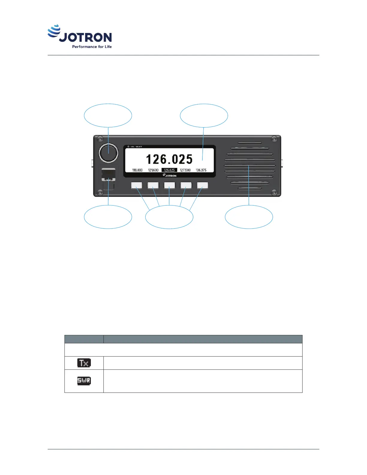
3.1 Front panel controls and connector
Mic/Headset
connector
Mic/Headset
connector
Scroll / Select
knob
Scroll / Select
knob
DisplayDisplay
Shortcut key sShortcut key s
LoudspeakerLoudspeaker
Figure 3: Front view of TR-910
3.1.1 Display
The display shows the most important operaonal parameters such as selected channel/frequency, modulaon
and indicator icons. In addion, the display will show various menus and submenus which can be navigated
using the scroll/select knob and shortcut keys on the front panel.
The indicator icons appear at the le and right side of the display during operaon. Some icons share posion
in the display and are with descending priority listed in the table below.
Table 14: Indicator icons
Icon Descripon
Le side area:
Indicates that the transceiver is keyed, and the radio is transming.
Indicates that the SWR on the antenna is above the threshold value (app. 3:1).
The transmier will reduce the output power to the predefined low power
level in order to protect the output stage.
20 jotron.com Doc. No.: 103614 TR-910 Operator Rev. AB