11
Jøtul F 370 U.S. 10036803_P12
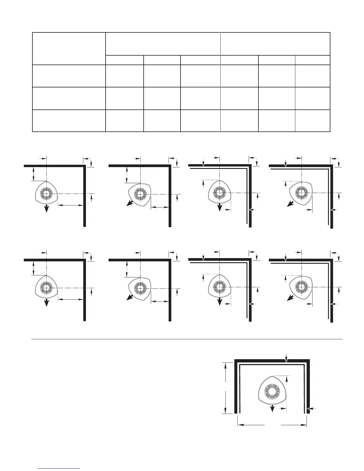
UNPROTECTED WALLS
PROTECTED WALLS
PER NFPA211 OR CAN/CSA -B365-M93
SIDE REAR
CORNER *
SIDE REAR
CORNER *
Single Wall Connector
A
22” / 560 mm
B
12” / 305 mm
C
16” / 406 mm
D
12” / 305 mm
E
12” /305 mm
F
8.5” / 216 mm
Double Wall Connector
G
22” / 560 mm
H
6” / 152 mm
I
16” / 406 mm
J
9” / 229 mm
K
4” / 102 mm
L
6” / 152 mm
Alcove w/ Double-Wall
Connector
N/A N/A N/A
M
12” / 305 mm
N
7” / 178 mm
N/A
Figure 9. Alcove clearance requirements.
Figure 8a. Clearance Diagrams.
4.4.3 Alcove Installations
The Jøtul F 370 can be installed in an alcove as diagrammed
in fig. 9.
1. The stove must be installed only with double-wall chim-
ney connector.
2. Wall protection must extend over the entire area.
3. Alcove floor protection must consist of a UL/ULC or
WHI listed Type 1 hearth pad or a non combustible ma-
terial.
4. Minimum Alcove Ceiling Height: - 72” / 183 cm
No alcove ceiling clearance reduction is permitted.
A
B
C
C
D
E
F
F
S I N G L E - W A L L C O N N E C T O R
30.75” / 781mm
21.75”
552mm
24.25”
616mm
20.75”
527mm
21.75”
552mm
16.75”
425mm
16.75”
425mm
24.25”
616mm
D O U B L E - W A L L C O N N E C T O R
H
G
I
I
K
J
L
L
14.25”
362mm
14.25”
362mm
13.75”
350mm
17.75”
451mm
24.25”
616mm
24.25”
616mm
30.75” / 781mm
15.75”
400mm
N
M
* Rear Exit chimney connector clearance supercedes the stove clearances listed above.
 Loading...