12
Jøtul F 370 U.S. 10036803_P12
5. Assembly
If the Rotation Kit will be installed, use the assembly
instructions provided with that kit.
5.1 Tools & Materials
• workgloves •safetyglasses
• tapemeasure •4mmhexkey
• powerdrillw/1/4”and3/8”drillbits
• 3/8”or10mmopenendorsocketwrench
• 9/16”or14mmsocketwrench
• ballpeenhammer(RearExitconnectiononly)
5.2 Unpacking the Stove
This product includes three boxes shipped on two pallets:
• 351006PedestalAssembly
• 351005FireboxAssembly-attachestothePedestal
Assembly
- includes a decorative Flue Outlet Cover Plate (for use
with a rear exit chimney connection), two cast iron Burn
Plates, and a stove mitt inside the Ash Pan.
• 157373AnchorBracket/OutletAdaptorKit
THEPEDESTALANDFIREBOXASSEMBLIESAREHEAVY!
Be sure to have assistance available when assembling
and installing this stove.
Inspect each assembly and immediately report any
damage to your local dealer.
1. From the bottom of the Pedestal Assembly, remove
and discard the foam doughnut gasket. Also remove
the bolt package from the pallet. These will not be
used in the U.S. and Canada.
2. From the Firebox Assembly:
Remove the Air Outlet Grille and Top Plate from the
stove. These simply lift off the main body.
Remove the Baffle Plate, both Side Panels, Rear Panel,
Shaker Grate, Bottom Plate, and Ash Pan from inside
of the firebox. See fig. 21 and parts list on pages 21-22.
3. Only if the Rear Exit flue connection is to be used:
•Drillaholeatthetwodimplelocationsinthecut-
out panels at the back of the stove (fig. 10, A).
•Placethewoodenwedge(fig.10,B)suppliedinthe
firebox as shown to support the side plates when the
outlet cut-outs are removed.
•Useaballpeenhammertoknockoutthepanels
from the back of the stove.
Figure 10. Removing the rear exit outlet knock-outs.
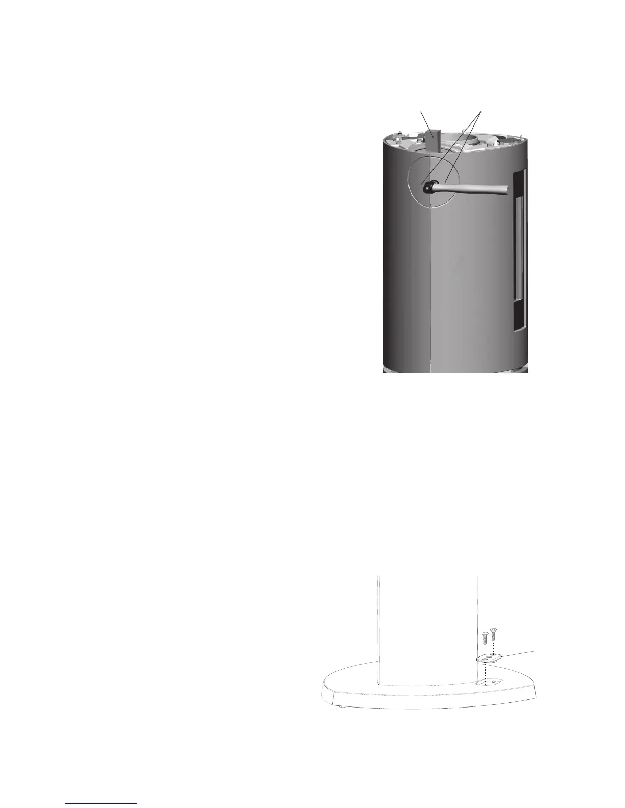
5.3 Attach the Anchor Bracket to the
Pedestal Base
1. Use a 4 mm hex key to remove the two countersunk
screws and cover plate from the pedestal base. See fig. 11.
2. Place the pedestal on its side and use the two,
M6 x 20 mm hex bolts to install the anchor bracket to
the underside of the base plate as in fig. 12.
Figure 11. Remove cover plate from the pedestal base.
Cover Plate