B4i-M
2 - 8
2.4. ELECTRONICS - STRUCTURE
2.4.1. INTRODUCTION
The electronic part of the apparatus is formed of two boards : the microprocessor + power pcb, where
every function is located and the user interface pcb with display and LEDs. The former is located inside the
body of the machine (fig. 2.3 or 2.5, item 7), whereas the second one is in the back of the front panel (fig.
2.3 or 2.5, item 6).
The electronic imbalance sensor is located on the motor stabilizer (fig. 2.3 or 2.5, item 2) and allows the
detection of and excessive imbalance due to the rotor loading.
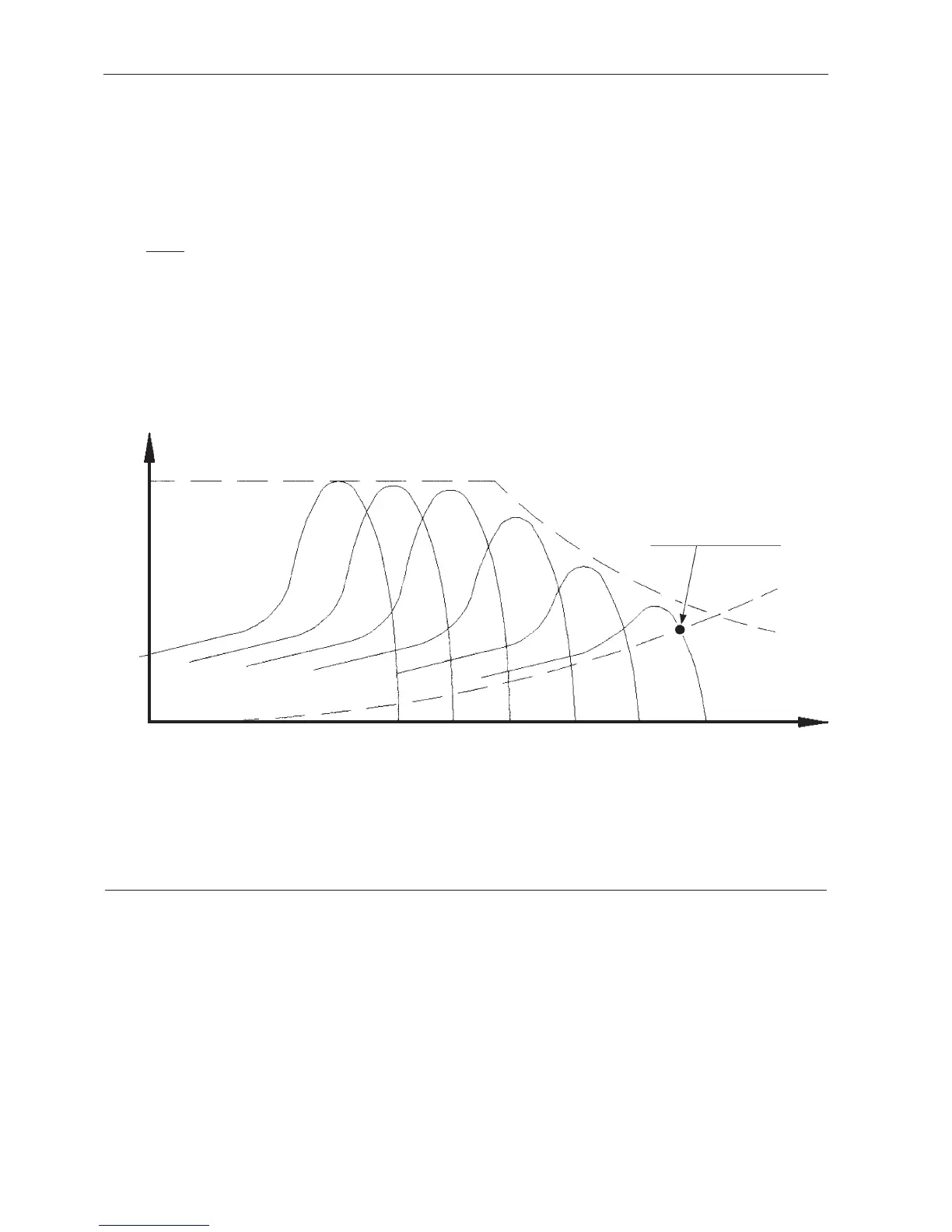
FIG. 2.7 - VARIATION OF THE CURVE OF THE MOTOR TORQUE AS A FUNCTION OF THE SPEED
C Max
Motor torque
Resistant torque
Torque
Operating point
Speed
Speed synchronisation is directly proportional to the frequency of the voltage supplied to the motor. Ns =
fx 60 (for a 2 pole motor).
The motor rotates at a speed N below the speed Ns.
Ns - N
Ns
= SLIPPAGE (the slippage varies between 1 and 3%).
To vary the speed, it is necessary to vary Ns and thus the frequency of the voltage supplied to the motor.
The torque characteristics will be translated on the speed axis. The supply voltage will vary within 0 to
12000 r.p.m. in order to keep the U/f ratio constant and not saturate the magnetic circuit.
 Loading...