ZONE 3
WARNING ! THIS ZONE IS AT MAINS VOLTAGE
This zone isolated from the microprocessor part by opto-couplers, is the electronic part related to the
power in the system. This zone includes :
-The 15 VDC power supply for the control electronics for this zone.
-The control circuit of the 6 basic signals of the IGBT module.
-The 3 PWR commands coming from the microcontroller
-The brake GBT with the command which permits flow through the braking resistor.-
-The diode bridge which, from the mains, charge the capacitor of the continous bus
-The relay which, controlled by the supply of power, then short circuits the resistance of the charge of the
capacitors of the continuous bus a few moments after switch-on.
-The module of 6 IGBTs and its heat sink which power the motor.
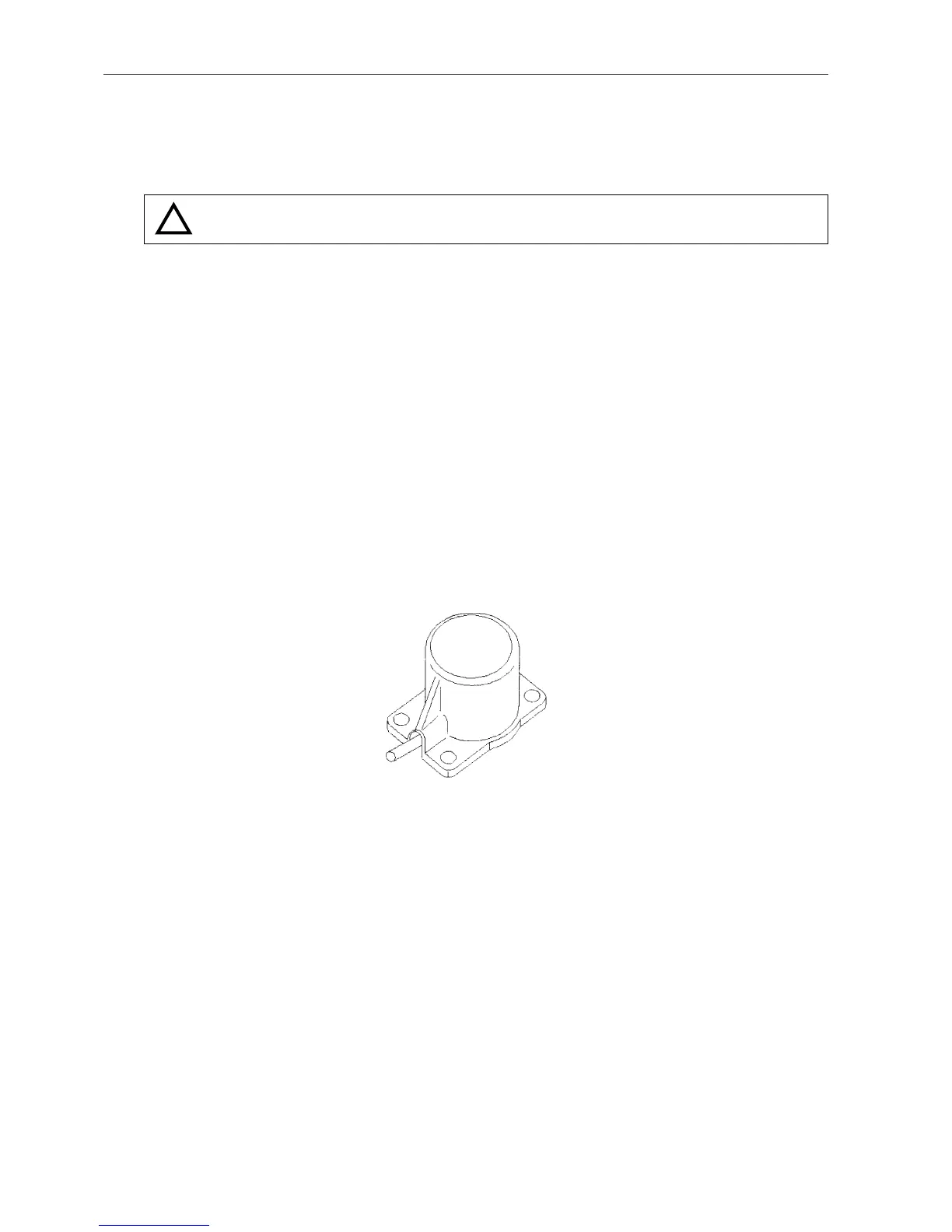
2.4.3.IMBALANCE SENSOR
As described in the introduction, this sensor allows the detection of an excessive imbalance in the rotor
loading.
A piezzo ceramic converts the energy created by the vibration into an electrical signal. After shaping, this
signal is sent to the microprocessor for the safety devices.
2.4.4.TACHO SENSOR
The tacho sensor is comprised of an optical sensor, which, generates two pulses per revolution.
2.4.5.TEMPERATURE SENSOR (BR4i)
After the shaping circuit , the signal is 1.23 Vcc (0°C) ±80 mV/°C
2.4.6.REFRIGERATION CONTROL BOARD (BR4i)
The board controls the power signal to the refrigeration group.
B4i-M
2 - 10
!
 Loading...