B4i-M
2 - 7
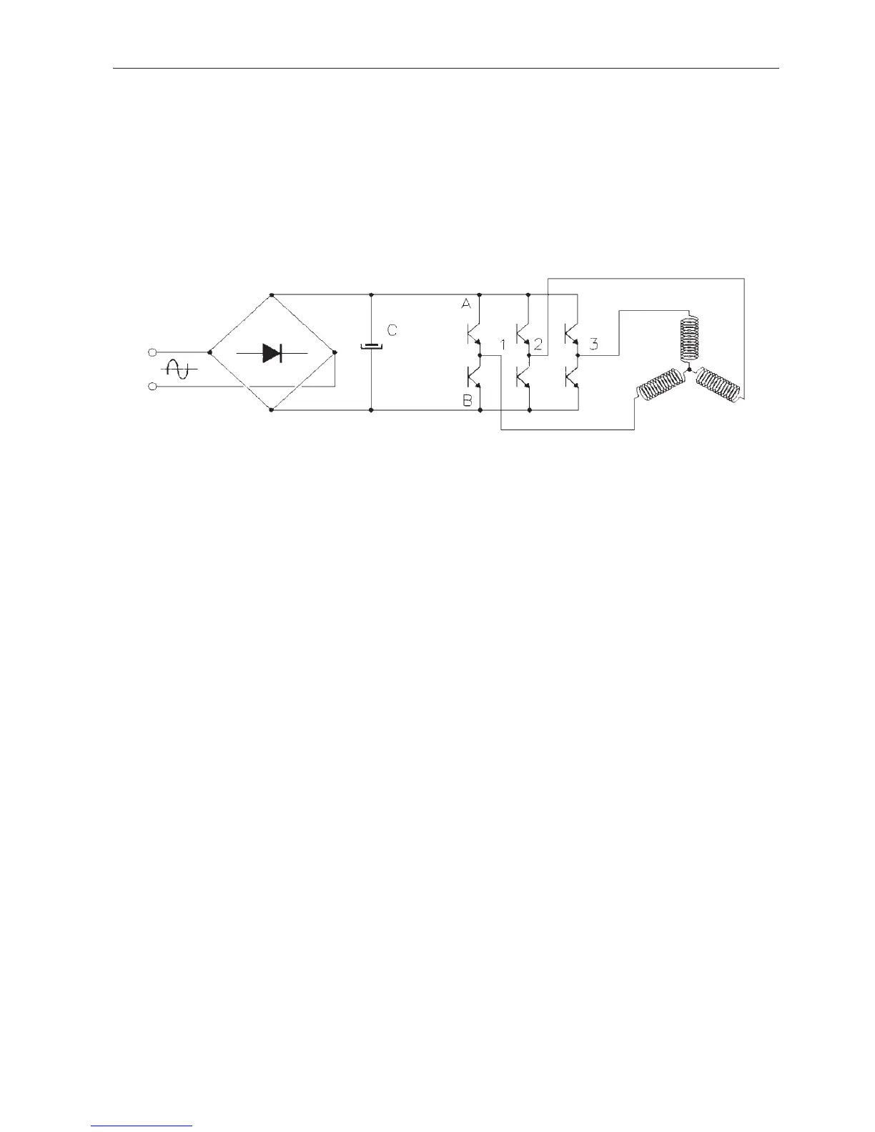
The voltage is rectified then filtered by C to supply the constant voltage +E. The value of the capacitor C is
high.
For a 230V - 50 Hz mains supply E = 230 √2 = 325 V
C = 470µF / 400 V
For a 120V - 60 Hz mains supply E = 120 √2 = 170 V
C 1500 µF / 200 V
The 6 transistors act as switches (open or closed).
These transistors commute at a fixed frequency (8 kHz).
To affect the voltage at R we act upon the commands of the transistors a and b, b always being the
opposite to a (a = closed, b = open). By changing the cyclic ratio (closed/open) we obtain a mean
sinusoidal value so we are able to vary the amplitude and frequency.
It is necessary that the pilot frequency must be elevated compared to the frequency of the generated
sinusoidal voltage. The latter is around 400 Hz at 24000 r.p.m. (f pilot / f sin = 10 at N max. speed).
In the same way, the voltages at points S and T will be sinusoidal between OV and +E and dephased by
2π/3 between them.
These 3 voltages are simple voltages varying between OV and +E. They are partly sinusoidal and partly
on a baseline situated at +E/2. Thus the O of the sinusoidal voltage corresponds to 50 % of the cyclic ratio.
The voltages applied to the motor phases are the compound voltages VR-VS, VS-VT,VT-VR and will vary
between + E and - E ([O-(+E) = -E]
Thus at the motor terminals are recreated the voltages whose amplitude is close to that of the mains.
2.3.3. POWER CONTROL
Three voltages, variable in amplitude and frequency, dephased by 2π/3, must be supplied from a 50 or
60 Hz single phase mains supply.
V MAINS
STATOR
 Loading...