EasyManua.ls Logo

JPS NXU-2B - Internal Jumper Configuration

JPS NXU-2B
70 pages
Print Icon
To Next Page IconTo Next Page
To Previous Page IconTo Previous Page
Loading...
NXU-2B Operations Manual
2-4
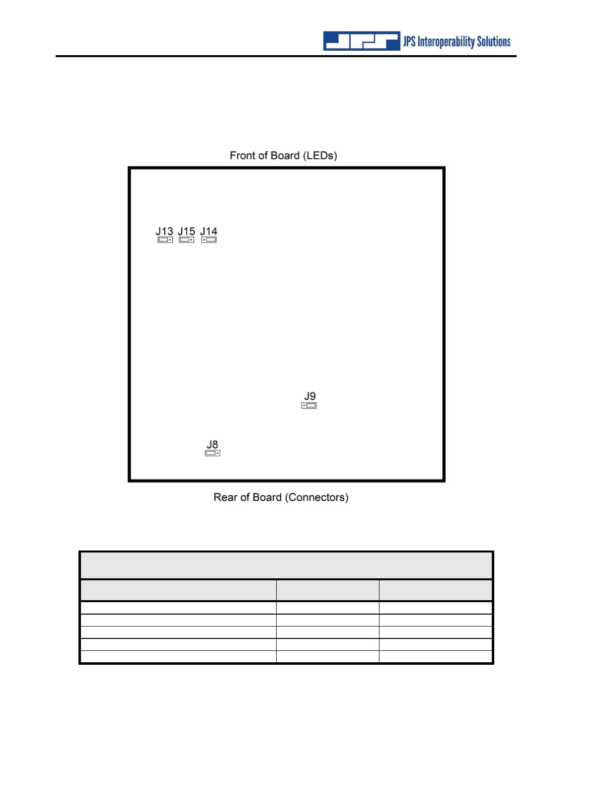
2.5.1 Internal Jumper Configuration
The illustration below shows the NXU-2B internal PCB jumper locations. The only reason to
open the unit is if the default settings are not optimal for your system. For the majority of
applications, the default jumper settings are sufficient and need not be changed.
Figure 2-2 NXU-2B Internal Configuration Jumpers
Table 2-1 NXU-2B Jumper Settings [Default Settings in Bold Text]
Jumper and Function
Left 2 Pins
Right 2 Pins
J8: Audio In Balanced/Unbalanced
Balanced
Unbalanced
J9: Audio In Impedance
600 Ohms
High Impedance
J13: E&M Return
Ground
AUXIN0
J14: PTT Source
Transistor open drain
Relay Contact
J15: AUXIN0 Pin Function
AUXIN0 input
E&M Return

Table of Contents

Related product manuals