NXU-2B Operations Manual
2-6
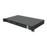
2.8 Rear Panel Connectors
Refer to Figure 2-1 for a view of the NXU-2B Rear Panel. All rear panel connectors are explained
in the section that follows, starting at the left side of the panel.
2.8.1 DC Input Connector, (+12 VDC INPUT)
The NXU-2B operates on a nominal +12 VDC. The power is applied to the +12 VDC INPUT
via the “Wall Cube” AC adapter provided with the unit.
2.8.2 Connection to Radio or Other Four-Wire Device (AUDIO/CONTROL)
The interface between the NXU-2B and associated radio or other audio device is made via the
Audio/Control connector on the rear panel. This is a female DB-15 connector.
Note: On the NXU-2A, which the NXU-2B replaced, an Audio Crossover Adapter was included.
This DB-15 male to DB-15 female adapter allowed the use of radio cables developed specifically
for the JPS ACU-1000 Intelligent Interconnect system to be used with the NXU-2A. It provided
a crossover of transmit and receive audio as well as COR and PTT control signals. You do not
need this adapter on the NXU-2B, as its audio port has been changed to match that of the ACU
product family, and cables designed specifically for the ACU products will work on the NXU-2B.