EasyManua.ls Logo

JRC JCY-1850 User Manual

JRC JCY-1850
73 pages
To Next Page IconTo Next Page
Page #1 background imageLoading...
Page #1 background image
SIMPLIFIED
VOYAGE DATA RECORDER
INSTRUCTION MANUAL
CODE: 7ZPJD0389A

Table of Contents

Other manuals for JRC JCY-1850

Questions and Answers:

JRC JCY-1850 Specifications

General IconGeneral
ManufacturerJRC
ModelJCY-1850
Measurement ParametersTemperature, Humidity
Humidity Range0% to 100% RH
Resolution (Temperature)0.1°C
Resolution (Humidity)0.1% RH
Communication InterfaceUSB
CategoryData Logger
Accuracy (Humidity)±3% RH
Battery Life1 year (typical)

Summary

Preface

Before Operation

SYMBOL MARKS

Explains international warning signs and their meanings.

Examples of Symbol Marks

Illustrates common warning symbols and their applications.

Warning Labels

Advises not to remove or alter equipment labels.

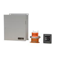
Outlook of system components

1. Operation

1.1 Outline of the Equipment

Describes the purpose of the equipment for accident prevention.

1.2 Configuration

Shows the standard configuration of the equipment.

1.2.1 System Diagram

Illustrates the system connections and components.

1.3 Starting and Stopping the System

Details the procedures for powering the system on and off.

1.3.1 Starting the System

Step-by-step guide to turn on all system components.

1.3.2 Stopping the System

Step-by-step guide to turn off all system components safely.

1.4 Operational Description

Explains the basic operational procedures and functions.

1.4.1 To Stop Recording Data onto the Protective Capsule Unit

Procedure for halting data recording to the capsule.

1.4.2 To Restart Recording Data onto the Protective Capsule Unit

Procedure to resume data recording to the capsule.

1.4.3 Backing Up the Data of the CF CARD

Steps to copy recorded data from CF card to a PC.

1.4.4 Actions to be taken at the time of an accident (Guidelines)

Guidelines for preserving data following a marine accident.

1.4.5 Stopping the Audible Alarm on the Operation Panel Unit

How to silence the system's audible alarm.

1.5 Recording Control Unit (NDV-1850)

Details the components and functions of the RCU.

1.5.1 Names of Parts of the Recording Control Unit (NDV-1850)

Identifies and describes the parts of the RCU.

1.5.2 Power Supply Unit

Explains the functions and operation of the PSU.

1.5.3 Data Processor Unit

Details the components and functions of the DPU.

1.6 Operation Panel Unit (NCG-169)

Describes the OPU's functions and user interface.

1.6.1 Names and functions of each part of the External Operation Board

Identifies and explains OPU controls and indicators.

1.6.2 How to operate the Operation Panel Unit (Normal mode)

Guide for operating the OPU in standard mode.

1.6.3 How to operate the Operation Panel Unit (on NSK mode)

Guide for operating the OPU in NSK mode.

2. Specification

2.1 Protective Capsule Unit: PCU (NDH-317)

Details the function, performance, and environmental specs of the PCU.

2.2 Recording Control Unit: RCU (NDV-1850)

Covers RCU performance, button operations, and LED indications.

2.2.1 Operation panel (Internal)

Describes internal OPU performance, buttons, and LEDs.

2.2.2 Data Processor Unit

Details the DPU's functions, performance, and interfaces.

2.2.3 Power Supply Unit: PSU

Outlines PSU functions, performance, and interfaces.

2.2.7 NSK interface

Specifies the NSK interface function and signal inputs.

2.2.8 Radar switching recording function

Explains radar switching for recording from two radars.

2.3 Operation Panel Unit: OPU (NCG-169)

Describes the OPU's function, performance, and environmental conditions.

2.4 Microphone Unit (NVT-161)

Details the function, performance, and environmental specs of the microphone.

2.5 Connection Box (NQE-3163)

Specifications for the waterproof junction box.

2.6 Waterproof Microphone Unit (NVT-162)

Specs for the waterproof microphone unit.

2.7 Radar Interface Unit (NWP-46)

Details the NWP-46 unit for high-resolution radar connection.

2.8 General Environmental Condition

Outlines general environmental conditions for S-VDR usage.

2.8.1 Location

Specifies usage conditions and unit installation locations.

2.8.2 Power supply environment

Details AC power supply input and frequency fluctuation ranges.

2.8.3 Environment

Lists environmental conditions for exposed and protected equipment.

3. Maintenance and Inspection

3.1 Daily Maintenance

Explains routine tasks for maintaining the equipment.

3.1.1 Cleaning

Instructions for cleaning the equipment safely.

3.1.2 Check of the expiry date of the battery

Procedure to check and manage battery expiry.

3.2 Periodic Inspection

Guidelines for yearly equipment inspections.

3.3 Troubleshooting

Provides guidance for resolving equipment malfunctions.

3.3.1 The Recording Control Unit (NDV-1850)

Symptom table for the Recording Control Unit's power supply.

Symptom Table for The Data Processor Unit (NDL-46)

Troubleshooting table for the Data Processor Unit.

3.3.2 The Operation Panel Unit (NCG-169)

Troubleshooting for the Operation Panel Unit.

ERROR CODE: "20" lights up.

Troubleshooting for error code 20 related to wiring.

ERROR CODE: "70" / "71" lights up.

Troubleshooting for radar signal errors (CH1/CH2).

4. After-sales service

4.1 To request the service

Guidance on how to request repair services for the product.

S-VDR Failure Check List

A checklist to help diagnose product failures before requesting service.

4.2 Disposal of unit

Instructions for proper disposal of the equipment.

4.3 Disposal of used battery

Safety and environmental guidelines for battery disposal.

5. Outline Drawings

5.1 Recording Control Unit: NDV-1850

Provides dimensional drawings and specifications for the RCU.

5.2 Operation Panel unit: NCG-169

Provides dimensional drawings and specifications for the OPU.

5.3 Protective Capsule Unit: NDH-317

Provides dimensional drawings and specifications for the PCU.

5.4 Connection Box: NQE-3163

Provides dimensional drawings and specifications for the connection box.

5.5 Microphone Unit: NVT-161

Provides dimensional drawings and specifications for the microphone unit.

5.6 Waterproof Microphone Unit: NVT-162

Provides dimensional drawings and specifications for the waterproof microphone.

5.7 Radar Interface Unit: NWP-46

Provides outline drawing for the Radar Interface Unit.

6. Block Diagrams

6.1 Recording Control Unit NDV-1850

Illustrates the internal block diagram of the Recording Control Unit.

6.2 Operation Panel Unit NCG-169

Shows the block diagram of the Operation Panel Unit.

6.3 Microphone Unit NVT-161

Illustrates the block diagram of the Microphone Unit.

6.4 Waterproof Microphone Unit NVT-162

Shows the block diagram of the Waterproof Microphone Unit.

6.5 Radar Interface Unit NWP-46

Illustrates the block diagram of the Radar Interface Unit.

Related product manuals