- 4 -
5 Panel Description
5.1 Front, top and side panels
○
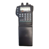
5 FUNCTION KEYS
[P0] to [P3] (See P.6 for details)
○
6 CH UP AND DOWN KEYS /
During standby condition, push to
select an operating channel.
○
7 TRANSMIT/BUSY INDICATOR
Lights red while transmitting; lights green
while receiving a signal, or when the squelch
is open.
○
8 PTT SWITCH [PTT]
Push and hold to transmit; release to receive.
5.2 Function display
①
②
③
④
⑤
Microphone
Function display
(See the following NOTE.)
○
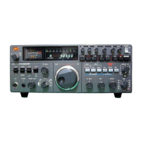
1 VOLUME CONTROL [VOL]
Turns power ON and adjusts the
audio level.
○
2 RED BUTTON [RED]
Monitor (See P.5 for details)
○
3 ANTENNA CONNECTOR
Connects the supplied antenna.
○
4 SPEAKER-MICROPHONE CONNECTOR [SP MIC]
Connects the optional speaker-microphone.(p.8)
[SP MIC] jack cover
NOTE: KEEP the [SP MIC]
ack cover attached to the
transceiver when the
speaker/microphone is not
used. (See p.3 for details)
NOTE:
If the speaker netting (for dust proofing)
becomes wet, dry it with a hair drier
(cool mode) etc. before operating the
transceiver. Otherwise the audio may
be difficult to hear for loss of the sound
pressure.
③
④
⑤
②①
○
1 OUTPUT POWER INDICATOR
Appears when Low 2 or Low 1 is selected.
○
2 AUDIBLE INDICATOR
Appears when "Tone SQL" is released.
○
3 KEY LOCK INDICATOR
Appears during the key lock function ON.
○
4 BATTERY INDICATOR
Appears or blinks when the battery power decreases to a specified level.
○
5 ALPHANUMERIC DISPLAY
Displays the operating channel number, tone squelch number, set mode contents, etc.