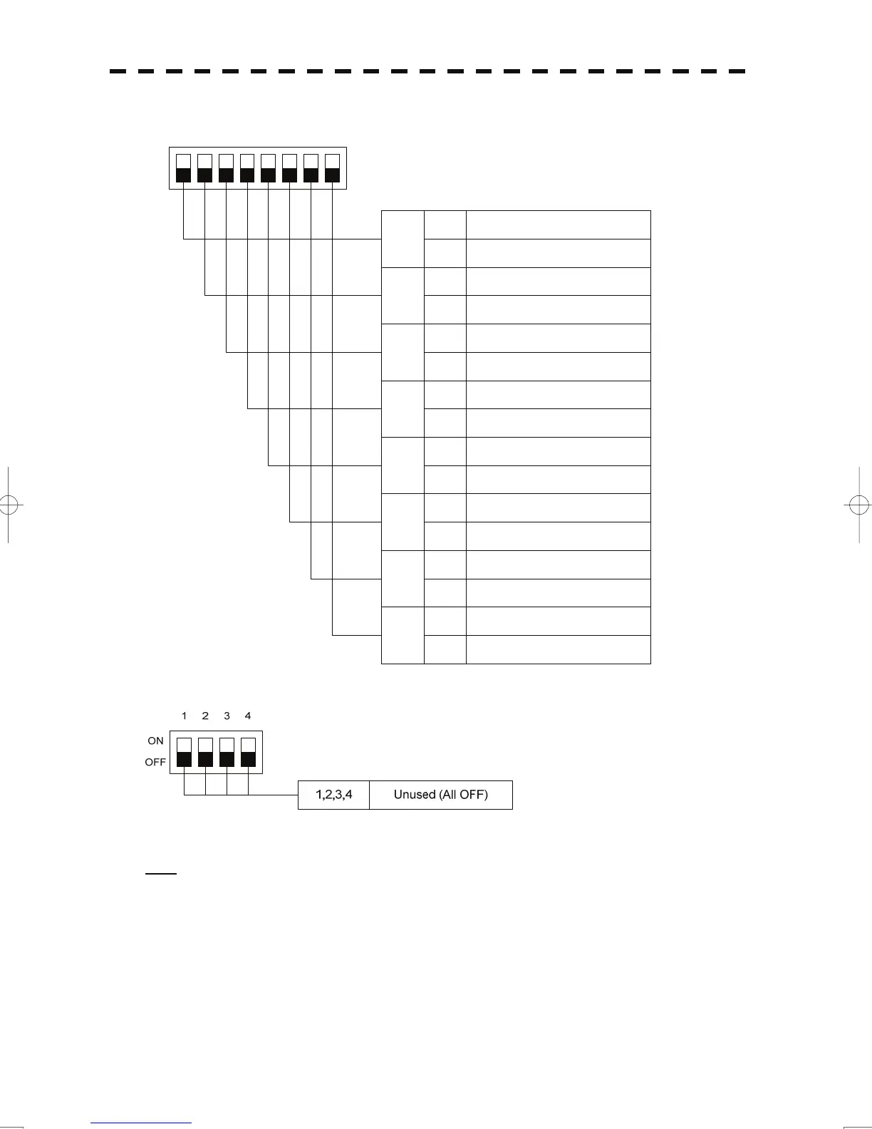
2) SW12 setting (radar connection settings)
1234
ON
OFF
8
Radar connection settings
ON No.4 scanner unit connected
OFF No.4 scanner unit not connected
5678
7
ON No.4 display unit connected
OFF No.4 display unit not connected
6
ON No.3 scanner unit connected
OFF No.3 scanner unit not connected
5
ON No.3 display unit connected
OFF No.3 display unit not connected
4
ON No.2 scannerunit connected
OFF No.2 scannerunit not connected
3
ON No.2 display unit connected
OFF No.2 display unit not connected
2
ON No.1 scannerunit connected
OFF No.1 scanner unit not connected
1
ON No.1 display unit connected
OFF No.1 display unit not connected
3) SW13 (unused)
Note: Before the DIP switches of the interswitch circuit can be set, the interswitch breaker must be turned
off in order to ensure safety operation.
A-11
 Loading...


