JMA-9100/7100 Installation Manual > 3.INSTALLATION OF DISPLAY UNIT > 3.10 CONNECTION WITH ALARM MONITORING SYSTEM
3-37
3
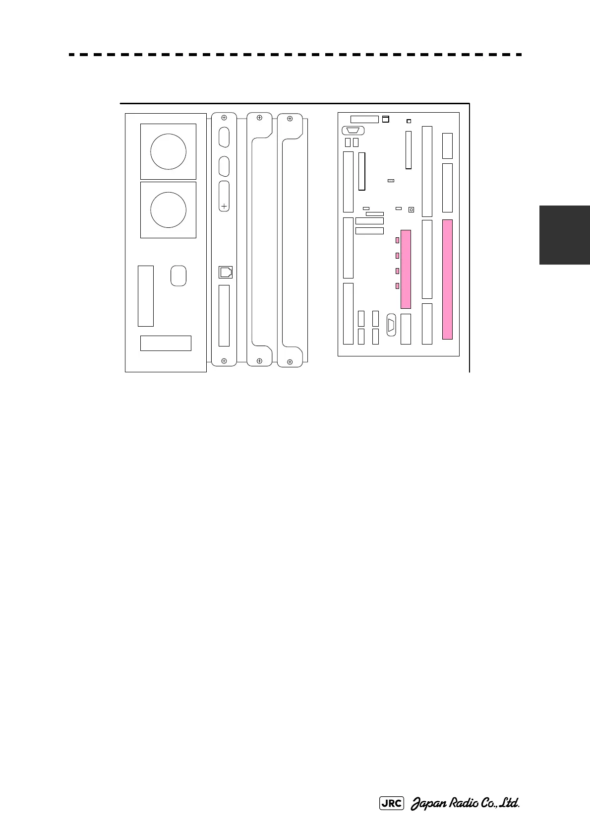
Fig 3-32: Arrangement in TB11-14, TB4501 and TB4401
Conditions of all of the signals can be checked by LEDs on terminal board circuit
CQD-2097. See 3.12.3Alarm Signal.
J4307(ISW-2CH
)
J4304
J4 306(I SW-1 CH)
J4301
TERMINAL BOARD
TB 2
J4313
J4309
J4314
J4302J4303
TB4101(ANT)
TB4301
(PWR SRC)
TB4401 (EXT RADAR)
TB4201 (ISW IN/OUT)TB4501 (OPTION)
TB4801 (LOG)
TB4701
(GYRO)
TB4601 (ALARM)
J4 31 0
J4312 OPE2
J4311 OPE1
TB1A TB1B
TB1C TB1D
J4308
ISW
J4315
J4305
PC430
COM
 Loading...


