JMA-9100/7100 Installation Manual > 5.OPTION UNIT > 5.1 INSTALLATION OF INTERSWITCH UNIT
5-3
5
5.1.3 Installation of interswitch unit
a. NQE-3141-2A
Basically, the interswitch unit is incorporated into the display unit and delivered
with the wiring completed.
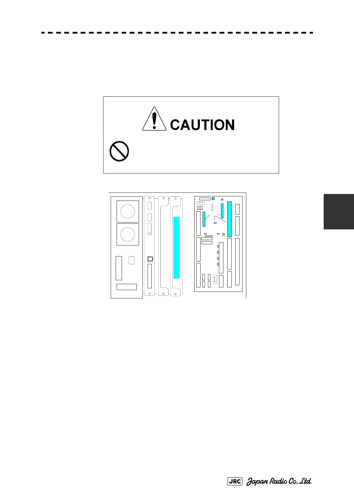
Fig 5-4: Device Arrangement
When incorporating interswitch unit NQE-3141-2A later, follow the procedures
below.
1)
Disconnect the cable (W404 H-7ZCRD1340A) connected between terminal board circuits
J4306 (ISW-1CH) and J4307 (ISW-2CH) located on the port-side radar display unit.
2)
Disconnect the cable (WZ,H-7ZCRD0970A) connected to connector J3 located on the
interswitch board (CCL-304R) CH1 port and connect it to terminal board circuit J4306.
3)
Disconnect the cable (WZ,H-7ZCRD0970A) connected to connector J3 located on the
interswitch board (CCL-304R) CH2 port and connect it to terminal board circuit J4307.
4)
Disconnect the cable (WZ,H-7ZCRD0971) connected to J1 in the power-supply section
(CBD-1675) mounted in the interswitch unit and connect it to terminal board circuit
J4308.
5)
Incorporate the interswitch unit into a vacant slot of the rack (right end, see Fig 5-4:
Device Arrangement).
Incorporate the interswitch unit into the port-side
radar display unit.
Turn off the switchboard breaker of both radars
before installing or replacing the interswitch unit.
Interswitch Unit (NQE-3141-2)
J43 07(IS W-2CH
)
J4304
J43 06(IS W-1CH)
J4301
TERMINAL BOARD
TB2
J4313
J4309
J4314
J4302J4303
TB4101(ANT)
TB430 1
(PWR SRC)
TB4401 (EXT RADAR)
TB4201 (ISW IN/OUT)TB4501 (OPTION)TB4801 (LOG)
TB4701
(GYRO)
TB4601 (ALARM)
J4310
J4312 OPE 2
J4311 OPE 1
TB1A TB1B
TB1C TB1D
J4308
ISW
J4315
J4305
PC430
Related ISW
Function
 Loading...


