Maintenance Guide
1-16
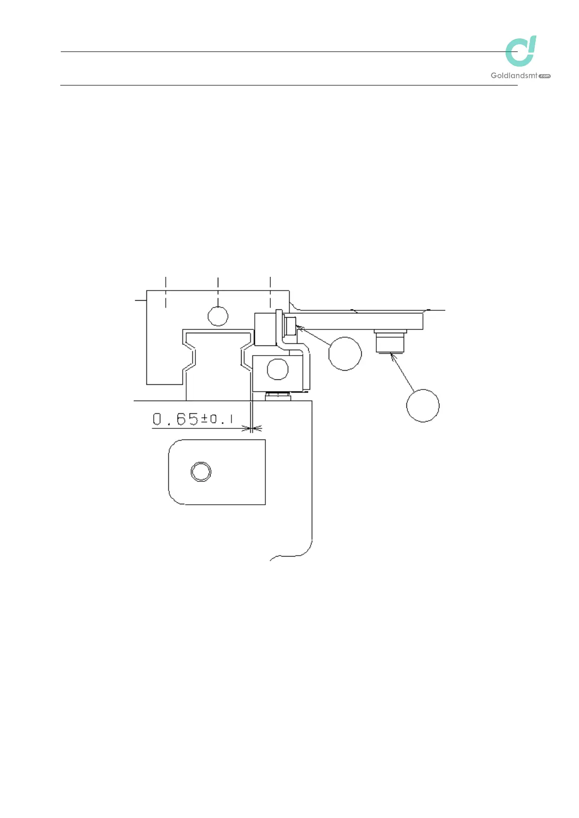
1-4-3. Clearance between the Sensor Head and the Y-Axis Linear Way
(for Y-Axis Only)
(1) Put a 0.65-mm clearance gauge in the clearance between the Y-axis linear way and
sensor head, and check that no play exists and that the clearance gauge is inserted
smoothly.
(2) If the clearance is not 0.65 mm in the check in (1) above, loosen the screw fixing the
sensor bracket (screw d shown in the figure below).
(3) Put a 0.65-mm clearance gauge in the clearance between the Y-axis linear way and
sensor head, and tighten the screw again.
(4) Carry out the check stated in above (1) above.
Clearance between the sensor head and the Y-axis linear way: 0.65 r 0.1 mm (for Y-axis only)
1
2

 Loading...


