−37 −
Adjustment Procedures Results of Improper Adjustment
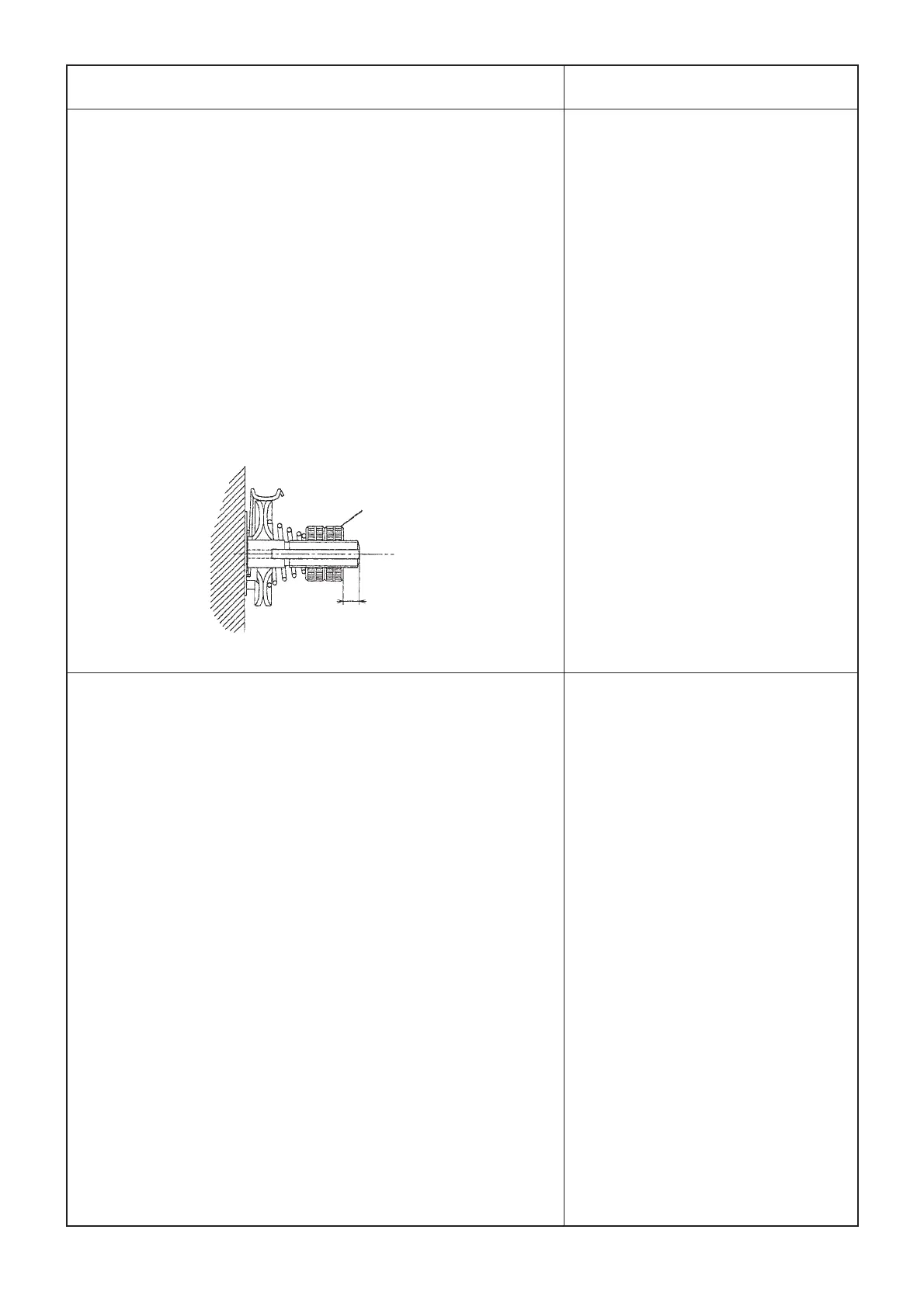
(3 to 4 mm)
1. Adjust so that thread breakage detecting plate 1 comes in
contact with thread take-up spring 2 without fail when the
machine head is not threaded. (Slack of the thread take-up
spring has to be 0.5 mm.)
2. When the stroke of thread take-up spring 2 has been
changed, loosen screw 3 and be sure to adjust thread
breakage detecting plate 1.
(Caution) Adjust so that thread breakage detecting plate 1
does not come in contact with any metallic part
other than thread take-up spring 2.
Assemble the nuts of the thread tension asm. as
shown in the figure.
1. Adjust so that a clearance of 0.5 to 1 mm is provided between
presser lifting lever 1 and stopper 2 when the presser lifting
solenoid works.
2. Loosen nut 4 in the presser lifting solenoid, turn the chain to
adjust the position, and securely fix the solenoid with shaft
section 3 of the presser lifting solenoid and nut 4.
(Make sure that presser lifting lever 1 comes in contact with
boss 5 of the bobbin thread trimmer driving arm when presser
lifting lever 1 has returned.
(Caution) When the needle thread trimer bounds even with
the aforementioned dimensions, adjust so that the
chain does not slacken when presser lifting lever
1 has returned.
(Assembling thread tension asm.)
Nut
™ If the detecting plate does not come
in contact with the spring, the needle
thread breakage cannot be
detected and the cloth cutting knife
works.
™ If the contacting force is too strong,
early breakage of the thread take-
up spring will occur.
™ If the clearance is small, presser
lifting lever 1 does not return to the
initial position and presser lifting
error will occur.
™ If the clearance is large, the needle
thread trimmer may bound when
presser lifting lever 1 has returned.