Adjustment
Procedures
Results
of
Improper Adjustment
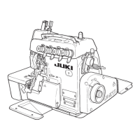
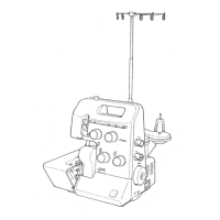
1. Disassembling
1) Remove top cover 8 and side cover
O.
2)
If
packing
t)
of the top cover has been adhered on the frame,
also remove packing
0.
3)
Remove needle front plug
CD.
4) Loosen setscrew
(I
of needle lubricating pin 8 and remove
needle lubricating pin
8.
5) Remove needle bar upper bushing cap screw
(I
and loosen
setscrew
41
in
the needle drive pin.
6) Fitting needle drive pin 8
in
the hole on the frame side, thrust
the pin until it can be drawn out.
2.
Adjustment
o If the oil wick is installed in the
1)
1;3ring
needle bar O to the lower dead point.
needle drive connecting link pin
2) Adjust oil wick e in needle drive pin 8
so
that it should be
inside the pin as the concave,
flush with the chamfered plane of the pin.
oil will not lubricated properly
(If oil wick O sinks inside the chamfered plane as the concave,
resulting in seizure.
oil will not be fed smoothly.)
o If
the
clearance
provided
3) Install needle lubricating
pin
8 in place with its oil inlet O faced
between the needle lubricating
above.
pin
and
the
needle
drive
4) Adjust with setscrew ti)
so
that the clearance between needle
connecting link is too small, the
lubricating pin 8 and needle drive connecting link O is
0.1
related components will come
in
mm. (It is convenient to use a
0.1
mm clearance gauge
or
the
contact with each other.
like.)
o
If
the
clearance
provided
between the needle lubricating
pin
and
the
needle
drive
connecting link
is
too large, oil
wll not be fed properly resulting
in seizure.
o If
the
oil inlet
does
not
face
upward,
oil
will
not
be
fed
resulting in seizure.
-39
-
From the Library of Superior Sewing Machine & Supply LLC
 Loading...