−62 −
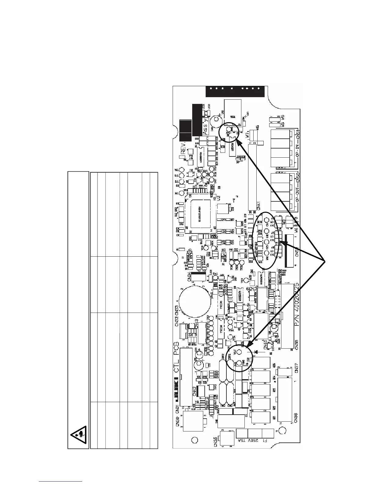
Appearance of CTL circuit board
Voltage check terminal
(3) Control voltage check terminal of CTL circuit board
Appearance of CTL circuit board assembled inside the front panel of SC-510 is as shown below.
Confirmation of each voltage whether it is abnormal can be performed since the control voltage check
terminals are set.
DANGER:
There is the possibility of the electric shock since the work is performed with the power ON.
Do not perform the work by any person other than the technicians who have electrical knowledge.
Check terminal Power main use Nominal voltage Remarks
+5V Circuit control +5V
+12V CP panel control ,
For optional electric power
+24V For optional electric power
VOUT For +33V/+24V solenoid drive +33v / +24V Voltage varies in accordance
with control state.
GND Ground for control circuit 0V
PGND Ground for control circuit 0V

 Loading...


