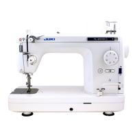
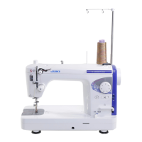
Name and Function of each component
■
Installing the foot controller
❶
❷
❸
❶
Insert the electric power cord plug into the corre-
sponding inlet.
❷
Insert the foot controller plug into the corresponding
inlet.
❸
Insert the power plug into the wall outlet.
CAUTION:
Perform these following steps when you are not us-
ing your sewing machine.
1. Be sure to turn OFF the power switch.
2. Be sure to remove the power plug from the wall
outlet.
3. Do not place a thing on the foot controller.
■
Attaching the knee lifter lever
The knee lifter lever allows the operator to lift/lower the
presser foot without releasing his/her hand away from
the material being sewn. (Lift of the presser foot: max.
12mm)
The knee lifter lever can be stored in the reverse side
of the auxiliary table.
WARNING (For U.S.A.,Canada only)
This appliance has a polarized plug (one blade wider than
the other). To reduce the risk of electric shock, this plug
is intended to t in a polarized outlet only one way. If the
plug does not t fully in the outlet, reverse the plug. If it
still does not t, contact a qualied electrician to install the
proper outlet. Do not modify the plug in any way.
CAUTION:
Be sure to turn OFF the power switch be-
fore plugging/unplugging the controller.
8
 Loading...