– 2 –
[2] Principle of Electric Brake
Three lead wires are drawn out from the motor. Lead wire is drwan out from the connecting point of the rotor coil
and stator coil to use the electric brake. MP detection printed circuit board asm. detects the number of slits of
the shield plate fixed on the motor shaft and is used to calculate the number of rotations of the motor and the
phase of main shaft. There are 72 pcs. of slits on the shield plate per circle. If the slit is converted into the main
shaft angle, the position can be measured (calculated) in a unit of 0.4 degrees. Comparing with the conventinal
model, the number of slits are increased and unevenness of rotation can be controllable. Principle of the
electric brake is called dynamic braking. The rotor becomes the dynamo and generates the electric power while
motor is rotating. Electric brake makes use of the fact that the brake is applied to the motor by consuming this
electric power. The higher the number of rotations becomes, the more the brake force becomes and the lower
the less.
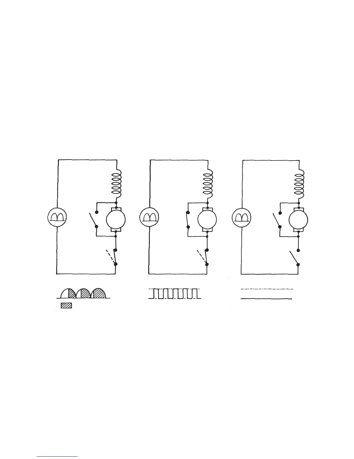
Motor drive simplified diagram
At the time of normal rotation of motor
Brake : Off
Motor drive : ON/OFF
Motor drive : Full wave phase control
: Motor drive ON
At the time of motor brake
Brake : ON
Motor drive : Oscillation
Motor drive : Oscillation
At the time of inertia stop or
normal stop of motor
Brake : OFF
Motor drive : OFF
Motor drive : OFF