–
18
–
General Mechanism
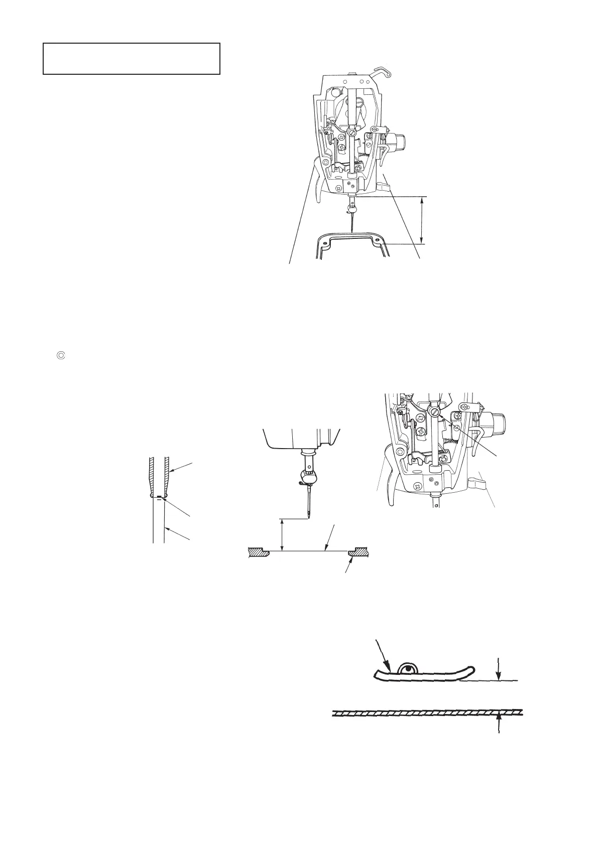
1. Height of needle bar bushing
○ Set dimension from top surface of throat plate
to lower end face of needle bar bushing to
67.0 ±0.1mm. (bushing : driving t)
2. Height of needle bar
○ Lower dead point of needle bar.
○ Attach length gauge (needle) of #14 needle to needle bar, and adjust dimension from tip of needle to install-
ing plane of throat plate on frame to 17.8 ± 0.1 mm.
○ Perform adjustment with needle bar connection setscrew.
Position of standard
Upper engraved line
A
on
❷
needle bar aligns
with bottom end of
❸
needle bar bushing when
needle bar is at lower dead point.
3. Height of presser foot
○ Adjust the height in the state that hand lifter lever
is raised.
○ Clearance provided between top surface of throat
plate and lower face of presser foot is 7.0±0.5
mm.
○ Perform adjustment with presser bar connection
setscrew.
Lower end face of needle bar
bushing
Top surface of throat plate
67.0 ± 0.1 mm
Needle bar
connection
setscrew
❷
❸
A
Frame
Installing plane of throat plate on frame
17.8 ± 0.1 mm
Throat plate
Presser foot
7.0±0.5 mm
 Loading...