10 Configuration level 1
48
Setpoint limits
setpoint start
setpoint end
➔ WLIMITS
➔ STARTVAL
➔ ENDVALUE
0.
400.
-1999—0 to +9999
-1999—400 to +9999
Manual output ➔ Y MANUAL 101. -100—100
101 = last output
Defines the output on over/
underrange
Manual operating
mode
➔ HANDMODE ENABLED
INHIBTD
enabled
inhibited
Self-optimisation ➔ TUNE ENABLED
INHIBTD
enabled
inhibited
Output 1 for
self-optimisation
➔ TUNEOUT1 RELAY
SSRELAY
ANOUTPUT
Relay
solid-state relay and logic output
analogue output
type of controller output 1 fro
self-optimisation
Output 2 for
self-optimisation
➔ TUNEOUT2 RELAY
SSRELAY
ANOUTPUT
Relay
solid-state relay and logic output
analogue output
type of controller output 2 for
self-optimisation
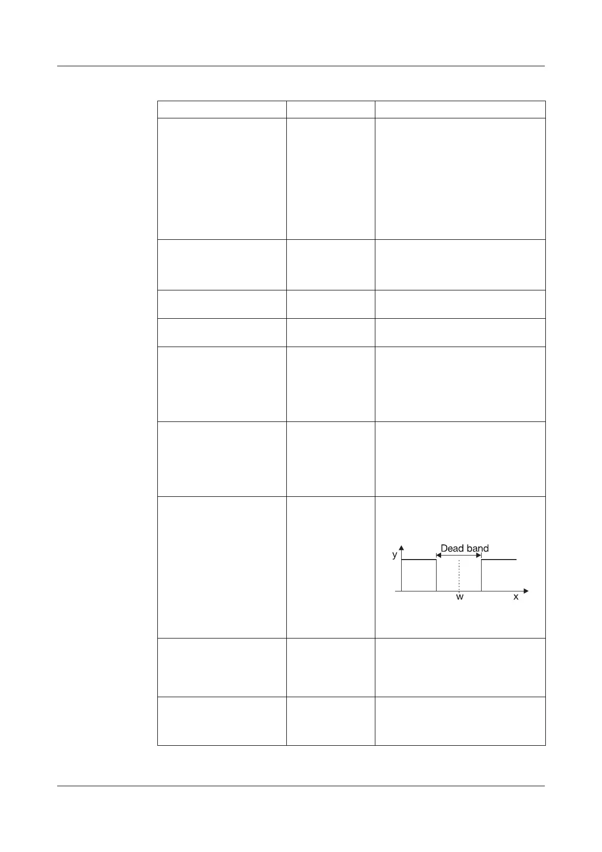
Deadband ➔DEADBAND 0. 0—999digit
serves to minimise the output
movement within the dead band;
e. g. with noisy signals.
The dead band is only effective
with controller structures with
I component.
Fuzzy control 1 ➔ FC1 0. 0—100
0 = fuzzy control off
Intensity of the fuzzy signal added
to the controller output to improve
the control quality.
Fuzzy control 2 ➔ FC2 30. 0—30—100
Influences the controller parameters
during activated fuzzy module to
improve the control quality.
CONFIG 1 ➔ CONTRL.
Parameter Value/selection Description
Factory settings are shown bold.
The setpoint limits are
ineffective with setpoint input
via the interface.
For external setpoint with cor-
rection, the correction value is
limited.