Do you have a question about the JUMO iTRON DR 100 and is the answer not in the manual?
Specifies environmental and site requirements for controller installation.
Guidelines for mounting multiple controllers adjacent to each other without interference.
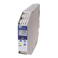
Instructions for detaching the controller from its mounting and its physical dimensions.
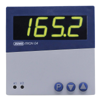
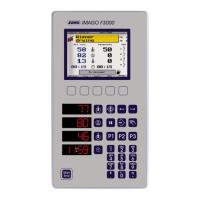
Describes the display states for controller, timer, and self-optimization modes.
Outlines navigation through different user interface levels for settings and control.
Details the procedures for starting, stopping, canceling, and acknowledging the timer function.
Covers configuration of input types, scaling, units, and process value correction.
Explains the setup and functionality of various logic inputs.
Details controller types, structures, and output behavior in fault conditions.
Configuration options and operational modes for limit comparators (alarm contacts).
Describes the ramp function's operation, including setpoint progression and timing.
Explains the automatic process of tuning controller parameters for optimal performance.
Describes how to restrict access to parameter and configuration levels using a code.
Details the timer's influence on control actions, events, and signaling.
Monitors input circuits for over/underrange and short-circuit conditions.
Specifies measuring ranges, accuracy, and connection circuits for analog inputs.
Details the function and connection configuration for logic inputs.
Describes the specifications for relay and logic outputs.
Information on controller types, structures, and analog-to-digital converter.
Covers the required input voltage ranges and power consumption.
Includes safety regulations, EMC, environmental conditions, and physical specifications.
| Display | LCD |
|---|---|
| Control type | On/Off, PID |
| Power Supply | 24 V DC |
| Input Types | Thermocouple, RTD, Voltage, Current |
| Output Types | Relay, voltage, current |
| Communication Interfaces | RS-485 |
| Input channels | 1 |
| Output channels | Up to 4 |
| Protection class | IP20 |
| Storage temperature range | -40 to 70 °C |
| Relative humidity | 10 to 90 % (non-condensing) |