4 Modbus protocol description
18
4.5 Device address
The device address of the paperless recorder can be set between 1 and 254
(decimal), see Chapter 3.4 Configuration of the serial interfaces, Page 12.
4.6 Function codes
Function
overview
The functions described as follows can be used to read out the measured
values and further device and process data from the paperless recorder.
A maximum of 31 paperless recorders can be addressed via the
RS 485 interface.
The device address 0 is reserved as the Modbus broadcast
address.
An instruction of the master to address 0 is carried out by all
slaves, but no response is transmitted by them (because this would
result in a data collision).
If only one paperless recorder is connected to the PC or notebook,
it can also be addressed via device address 255 (even if a different
device address is configured). The paperless recorder always
responds to instructions using device address 255.
In the transmission protocol, the address is specified in the
binary format (hexadecimal).
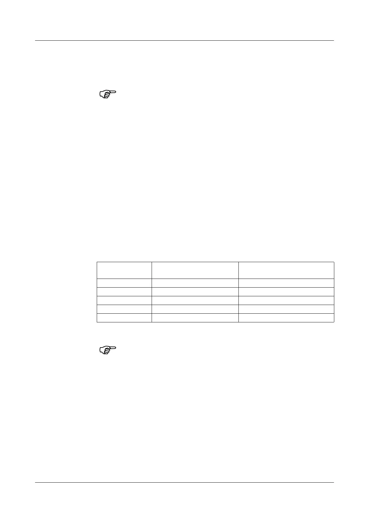
Function
number
Function Limitation
0x01 or 0x02 Read n bit max. 256 bits (16 bytes)
0x03 or 0x04 Read n words max. 127 words (254 bytes)
0x05 Write one bit max. 1 bit
0x06 Write one word max. 1 word (2 bytes)
0x10 Write n words max. 127 words (254 bytes)
Please refer to Chapter 4.9 Error messages, Page 28, if the paperless
recorder does not react to these functions or emits an error code.

 Loading...