How to Set Up Your SRX550 High Memory Services Gateway
5
c. Remove the clear plastic cover from the terminal studs on the faceplate.
d. Remove the screws on the terminals by using a Phillips (+) screwdriver,
number 2.
e. Secure each positive (+) DC source power cable lug to a RTN (return)
terminal. Secure each negative (–) DC source power cable lug to a -48V
(input) terminal.
f. Replace the clear plastic cover over the terminal studs on the faceplate.
g. Remove the tape from the switch handle of the circuit breaker on the panel
board that services the DC circuit and switch the circuit breaker to the ON
(|) position.
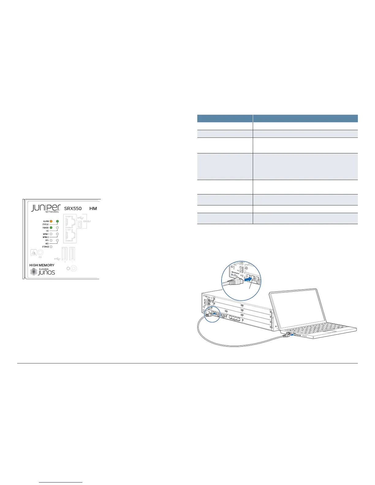
3. Note the following LED indications. Wait until the STATUS LED is solid green
before proceeding to the next step.
7
LED State
Power • Solid green (receiving power).
STAT US • Solid green (operating normally).
ALARM • Amber (operating normally–the LED might glow amber
if a rescue configuration is not set. This is not a panic
condition).
MPIM-1 and MPIM-2 • O (Mini-PIM not present or not detected).
• Solid green (Mini-PIM is operating normally).
• Red (Mini-PIM hardware failure or counterfeit check
failed).
HA • O (HA not enabled).
• Solid green (all HA links are available).
RPS • Solid green (redundant power supply is operating
normally).
ACE • The ACE LED is not functional.
STORAGE • Solid green (the services gateway is transferring data to
or from the optional storage device).
Connect the Management Device
1. Connect any of the network ports numbered 0/1 through 0/5 on the services
gateway to the Ethernet port on the management device, using an RJ-45
cable.
 Loading...


