Chapter 7---Troubleshooting
7-14
Model 250 Service Manual
Image Path
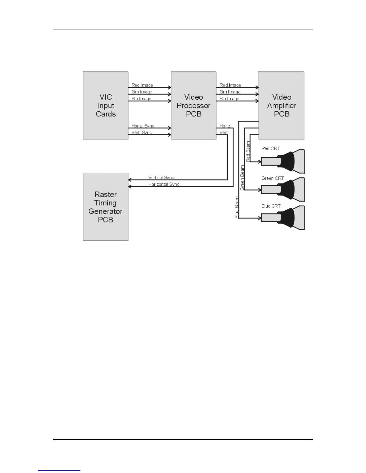
Figure 7-11
RGB Image path from VIC to CRT.
The image signals can be in the form of separate red, green and blue component
signals with separate horizontal and vertical sync signals or they can be a
composite image signal with all the image and sync signals combined into one
input signal. The image signals, if not already separate, are separated into red
green and blue color components, and horizontal and vertical syncs in the VIC.
The separated image and sync signals go to the Video Processor PCB. In the
Video Processor PCB the image signals are modified with Brightness, Contrast,
Gamma Correction, Sensitivity and Threshold. The modified image signals go to
the Video Amplifier PCB where they are go through an amplifier and on to the
CRTs.
The horizontal and vertical sync pulses are routed to the Raster Timing Generator
PCB. In the case of Sync-on- Green type sync pulses, the horizontal and vertical
syncs are stripped from the green image signal in the Video Processor PCB.