Chapter 5---Electronics
5-4 Model 250 Service Manual
!
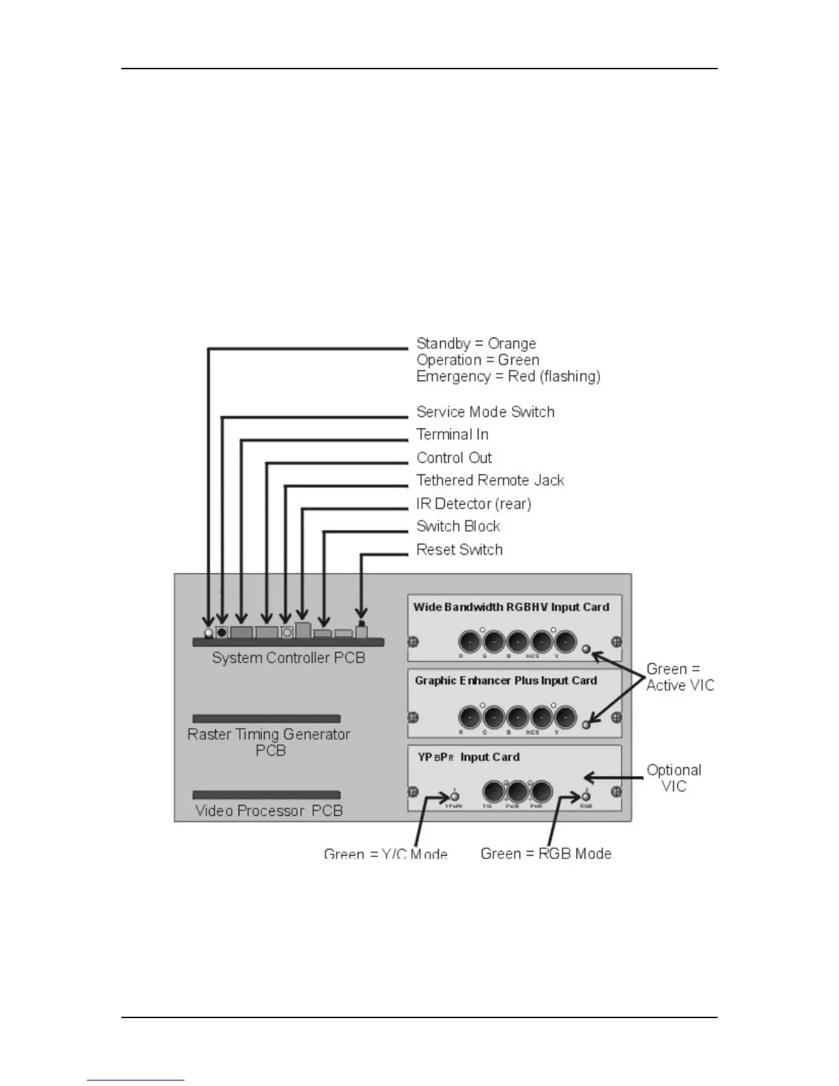
I/O control for VIC selection
!
Two RS-232 serial interface ports
!
Infrared (IR) remote control interface. Accepts input from front or rear IR
detectors.
!
External 3 color system status LEDs. Green indicates normal, yellow is
standby and red indicates a fault condition.
!
External Service Mode Switch. Pressing this switch during a power-up
sequence brings the system up in a diagnostic mode (for maintenance)
rather than a normal operating mode.
Figure 5-3
Rear of Electronics Module with rear cover and panel removed.