Chapter 5---Electronics
Model 250 Service Manual 5-9
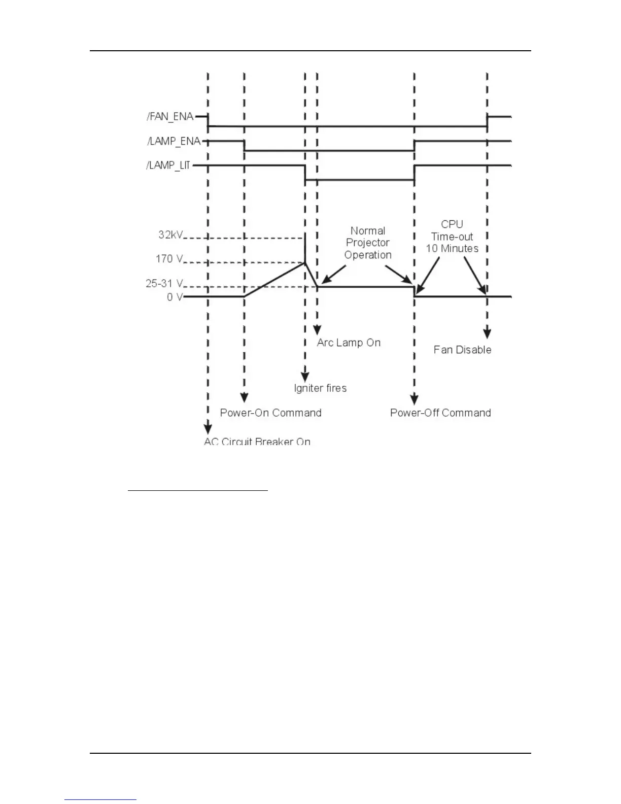
Figure 5-6
Power On timing sequence.
Normal Operation Functions
During normal projector operation, the System Controller PCB receives
commands through the remote control, tethered remote control, or a PC.
Commands issued from the IR remote controls are received through IR Detectors
located on the front and rear of the projector. Commands issued from a PC,
Laptop, or Tethered Remote Control are received through the RS-232 serial
interface ports.
The two RS-232 ports, labeled Terminal-in and Control-out, are functionally
almost identical. Both ports can be used to interface with computers, switchers, or
other remote controlling devices using a null modem cable. The difference is,
importing and exporting of configuration data can only be performed through the
Terminal-in. The dipswitch on the back of the System Controller PCB controls
the baud rate (see Figure 7-2).
The System Controller PCB enables the Video Processor PCB to select between
an internal and external source through the OVERLAY signal. The System