Chapter 5---Electronics
5-20 Model 250 Service Manual
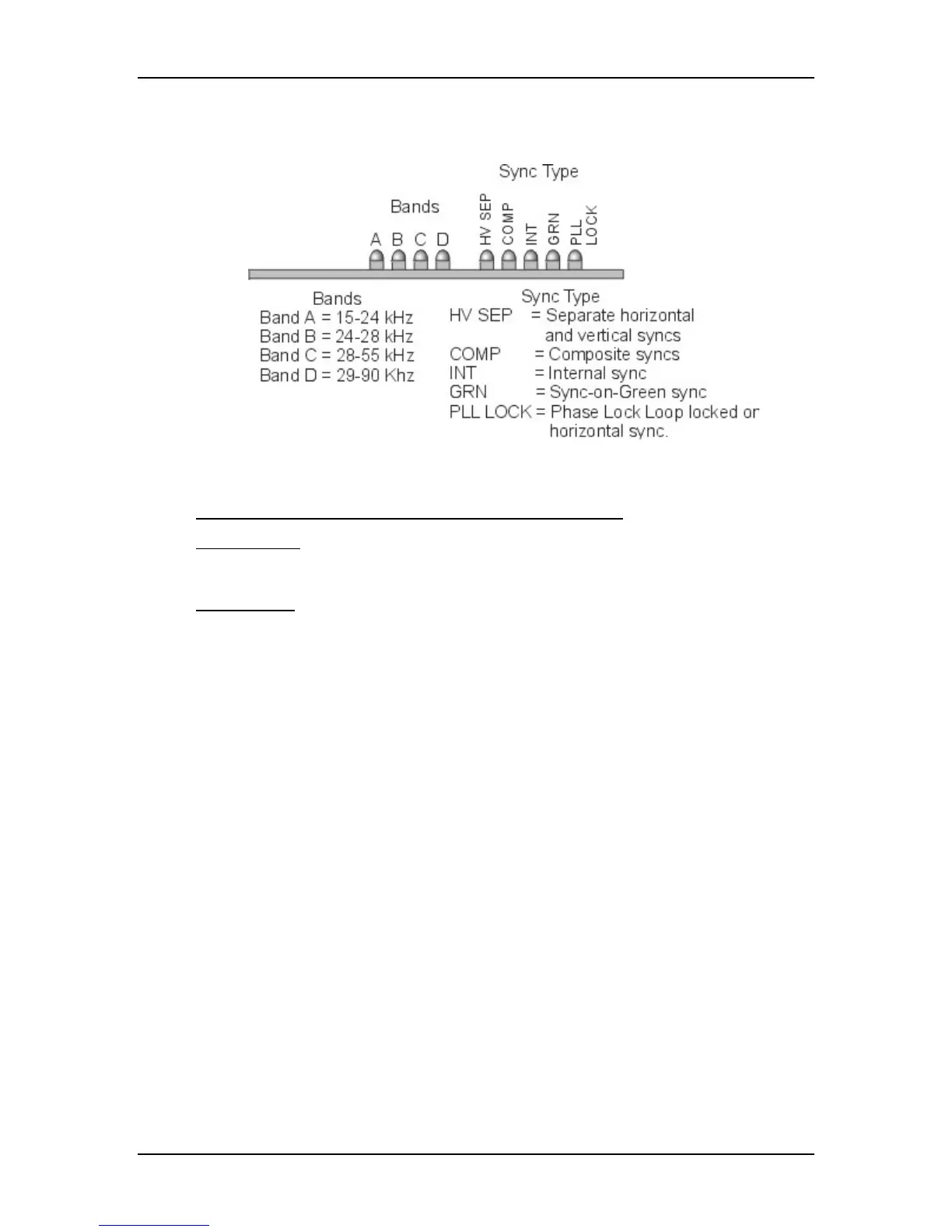
Vertical Deflection PCB to break the range of horizontal scan frequencies into
four smaller ranges called bands (see Figure 5-12).
Figure 5-12
LEDs on the Raster Timing Generator PCB.
Raster Timing Generator PCB - Remove and Replace
Tools Needed
#1 Pozi-drive Phillips-head screwdriver
Parts Needed
Raster Timing Generator PCB - p/n 105238
To remove the Raster Timing Generator PCB:
1.
Power OFF the projector by IR Remote or PC, and allow the cooling fans
to run until they shut off automatically.
2.
Turn the AC Circuit Breaker to the OFF position and unplug the AC
Power Cord.
3.
Disconnect all the external source video cables and control cables.
4.
Remove the rear cover.
5.
Remove the Back Panel. Remove the nine Pozi-drive Phillips-head
retaining screws using the #1 Pozi-drive Phillips screwdriver.
6.
Pull the black Card Extractor handles back to disconnect the Raster
Timing Generator PCB connector and pull the PCB out of the Electronics
Module.
7.
Reverse the procedure to install the Raster Timing Generator PCB.