CONNECTIONS
TABLE OF CONTENTS
CONNECTIONS
ConnectionsChecklist................ 5
Frontang RearPane_D_agrsms .......... 5
Cable & VCR Connections............. _ 6
Connectmgto a DVD Player............. 7
Connecting to a Camcorder............. 8
Connectingto anExtornalAmplifier......... 8
Connectingto JVCAVCompu LinkEX
CaPable G_npcnents ............. 9
GETTING STARTED
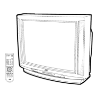
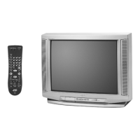
RemoteControls......... : ......... 10
Power......................... 11
AdjustingVc4urne .................. 11
ChangingChannels ................ 11
Seleng the CATVand VCR codes ........ 12
MENU FUNCTIONS
Symbols Used in thisGuile ............ 14
Onscreen Menus................... 14
Plug In Menu ..................... 15
Language
AutoTunerSetup
Set C,_ck .................. 16
Finish
Inibal Setup ..................... 17
Cha_nst Summary
Channel Guard-Lock
V_hip .................... 18
SetLock Code .............. 21
PfctureAdjust .................... 22
T_t
Cok_
Picture
Bt_ht
Detail
Noise Mut#lg
Set VideoStatus
Sound Adjust.................... 23
Treble
Ba_,_e
MTS (Mul_annst Stereo Sound)
Some SoundAdvice
Clock/Timers ..................... 24
On/Off Tkner
InitialSetup ...................... 25
)3/Spea_r
Aud_ Out
Cm'_ooner,t-/n
Ck;_sdCaptk:w
BUll"ON FUNCTIONS
Menu Button ..................... 26
Exit .......................... 26
Display ........................ 26
Video Status ..................... 26
Sleep Timer ...................... 26
BBE .......................... 27
Hyper SurrOund................... 27
TV/Video ....................... 27
100+.......................... 27
VCR Buttons ..................... 27
Muting......................... 27
Return+ ....................... 27
Number Buttons(10 Key Pad) ........... 27
PIPOrVM_ve ..................... 28
Freeze......................... 28
Swap ......................... 28
Channel -/+ for PIP.................. 28
Source ........................ 28
APPENDICES
Troubleshooting................... 29
umited Warranly................... 30
AuthorizedSor_k:eCenters............. 31
Spec fflesticP..s.................... 32
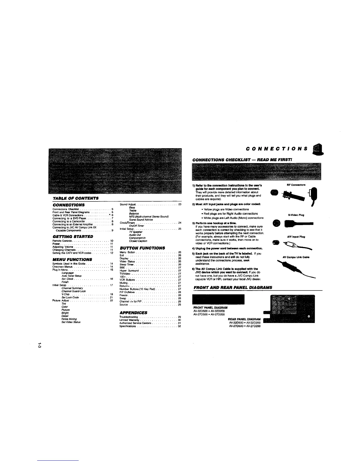
CONNECTIONS CHECKLIST -- READ ME FIRST!
1) Refer to the €onnection Inntructlons In the uler'l
guide for each component you plsn to connect.
They will provide more detailed informs[ion about
their products, and they will tollyou what plugs and
cables are mquirab.
2) Most AN input jacks and plugs sre cntor coded:
• Yellow plugs are Video connections
• Red plugs are fo_Right Audio connections
• Whha plugs are Left Audio (Mono) connections
3) Pertorm oils hookup nt i dine.
if you have many accessories to connect, make sure
each connection is correct by checking to see that it
works propeity before attempting the ne)d connection.
(For example, eiweys start withthe RF or Cable
connections, make sure it WORKS.IP_n move o_ to
video or VCR connections.)
4) Unplug the power cord between each connection.
5) Each Jack on the back of the TV is labeled. If you
resd these irmb_cticqlsand still do notfully
understand the connectio_ process, seek
assistance.
RF Connectors
S-Vldeo Plug
0
AN Input Plug
AV Compu Unk Cable
6) The/IV Compu Unk Cable hi supplied with the
JVC devlce which you want to (=ollneCL If you do
not have one, but you do have a JVC Compu Link
capable VCR o{ HiR, contact your locei JVC deaJe_
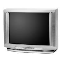
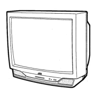
FRONT AND REAR PANEL DIAGRAMS
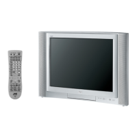
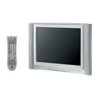
FRONT PANEL DIAGRAM
AV-32D500 • AV_2D200
AV-27DS00 • AV*27D2CO
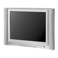
REAR PANEL DIAGRAM
AV-32D500 • AV-32D200
AV-27D500 • AV-27D200
CO
 Loading...