_ CONNECTIONS
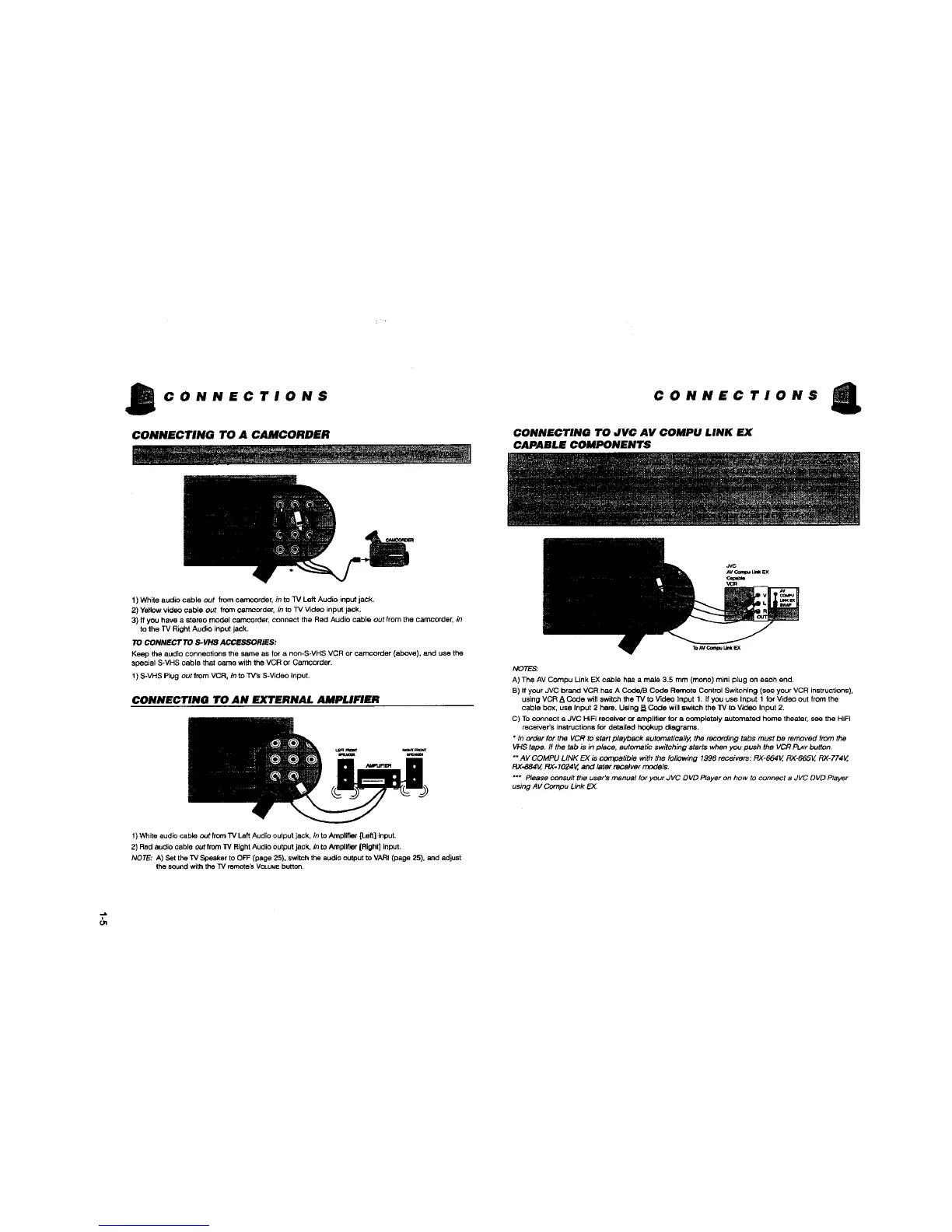
CONNECTING TO A CAMCORDER
CONNECTIONS
CONNECTING TO JVC AV COMPU LINK EX
CAPABLE COMPONENTS
1) White audio cable out from carncorder, in to TV Left Audio input jack.
2) Ye_towvideo cable out from camcorde_ _ to TV V_deo input jack.
3) If you have a stereo model oamcorder_connect the Red Audio cable out from the Carncorde_ in
to the TV Right Audle input jack.
TO CONNECT TO S-VHS ACCESSORIES:
Keep the audio connections the same as for a non-S*VHS VCR or camcorder (above), and use the
special S-VHS cable that catTm with the VCR or Carncorder.
! ) S-VHS Plug out from VCR. in to TV'S S-Video input.
CONNECTING TO AN EXTERNAL AMPLIFIER
NOTE_
A) The AV Compu Link EX cable has a male 3.5 mm (mono) mini plug on each end.
B) If your JVC brand VCR has A Code/B Code Refrtote Control Switching (see your VCR instructions),
using VCR A Code wi]] switch the TV to video Input 1. If you use Input 1 for Video out frownthe
cable box, use Input 2 here. Using B Code will switch the TV to Video Input 2.
C) Toconnect a JVC HiFi receiver or amplifier for a completely automated home theater, see the HiFi
receiver's instructions for detailed hookup diagrams.
• In order for the VCR to start playback automatically, the recording tabs must be removed from the
VHS tape. ff the tab is in place, aut_natic switching starts when you push the VCR P_Y button.
" AV COMPU LINK EX is compatible with the following 1998 receivers: RX-664V, RX*665V, RX-774V,
RX-884V, RX-1024V, and later _tver models.
"** Please consult the user's manual for your JVC DVD Player on how to connect a JVC DVD Player
using AV Compu Link EX
1) 'v%_iteaudio cable out from TV Left Audio output jack, in to Amplifier[Left] input.
2) Red audio cable out Ifom 33/Right Audio output jack. in to Amplifier[Right] input.
NOTE: A) Set the T,/Speaker to OFF (page 25). switchthe audio output to VARI (page 25), and adjust
the soundwith the TV remhte_ VCt.UMEbutton.
Gq
 Loading...