(No.YA243)1-23
4.8 ADJUSTMENT PROCEDURE
4.8.1 CHECK ITEM
4.8.2 FOCUS
4.8.3 DEFLECTION CIRCUIT
Item
Measuring
instrument
Test point Adjustment part Description
B1 VOLTAGE DC voltmeter S1 Connector
1-pin : TP-E
5-pin : TP-91B
[MAIN PWB]
(1) Receive the black and white signal. (color off)
(2) Connect the DC voltmeter to the 1-pin and 5-pin of
S1 connector.
(3) Confirm that the voltage is DC134.5V±2V.
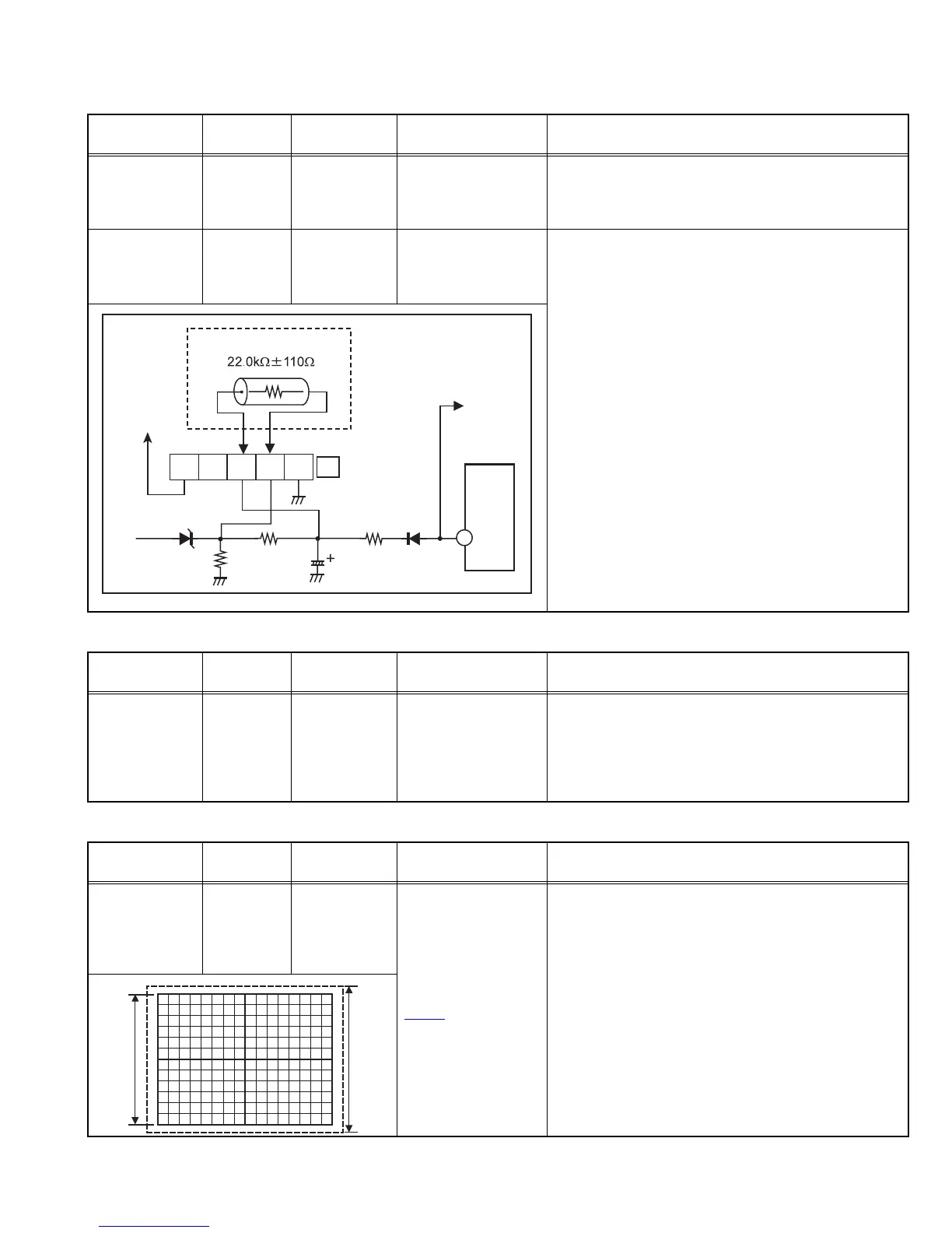
HIGH VOLTAGE
HOLD DOWN
Resistor
(22.0k
Ω
, 1/4W)
S1 connector
2-pin : X-RAY2
3-pin : X-RAY1
[MAIN PWB]
• After repairing the high voltage hold down circuit. This
circuit shall be checked to operate correctly.
(1) Turn the power switch to on.
(2) Refer to the figure, connect the resistor between S1
connector 2-pin and 3-pin.
(3) Make sure that the screen picture disappeares.
(4) Disconnect the power plug.
(5) Remove the resistor.
(6) Again connect the power plug.
(7) Turn the power switch to on.
(8) Make sure that the normal picture is displayed on the
screen.
HVT
HEATER
4
CONNECTOR
RESISTOR
S1
3 2 1
B1
45
Item
Measuring
instrument
Test point Adjustment part Description
FOCUS Signal
generator
FOCUS VR
[In HVT]
(1) Receive the crosshatch signal.
(2) While watching at the screen, adjust the FOCUS VR
to the vertical and horizontal lines will be thinnest
and sharpest center horizontal line.
(3) Make sure that the picture is in focus even when the
screen gets darkened.
Item
Measuring
instrument
Test point Adjustment part Description
V. SIZE /
V. POSITION
(4:3)
Signal
generator
Remote
control unit
[2.DEF (D)]
D05: V PHASE
D07: V SIZE
D11: VS CORR
D13: V LIN
V. CENTER SW
(S1421
)
[MAIN PWB]
(1) Receive the crosshatch signal.
(2) Select 2.DEF(D) from the SERVICE MODE.
(3) Select < D05 > (V PHASE).
(4) Set the initial setting of < D05 >.
(5) Adjust V. CENTER SW to agree the vertical center
with display center.
(6) Select < D07 > (V SIZE).
(7) Adjust < D07 > to the vertical screen size become
setting value is 92%.
NOTE:
• Bottom is to be located within the 85%-95% range.
• When vertical linearity is not even, adjust < D13 > (V
LIN) and < D11 > (VS CORR) to vertical linearity
Screen
size
Picture
size
100%
 Loading...