(No.MB177)1-11
3.1.17 Removing the power transformer 3 with the power 1 board
(See Fig.22)
• Prior to performing the following procedure, remove the top
cover, side panels, stay bkt, regulator board, power
transformer 1 and power transformer 2.
(1) From the top side of the main body, disconnect the wire
from the connector CN41
on the power 1 board.
(2) Remove the two screws U attaching the power transformer
3.
Fig.22
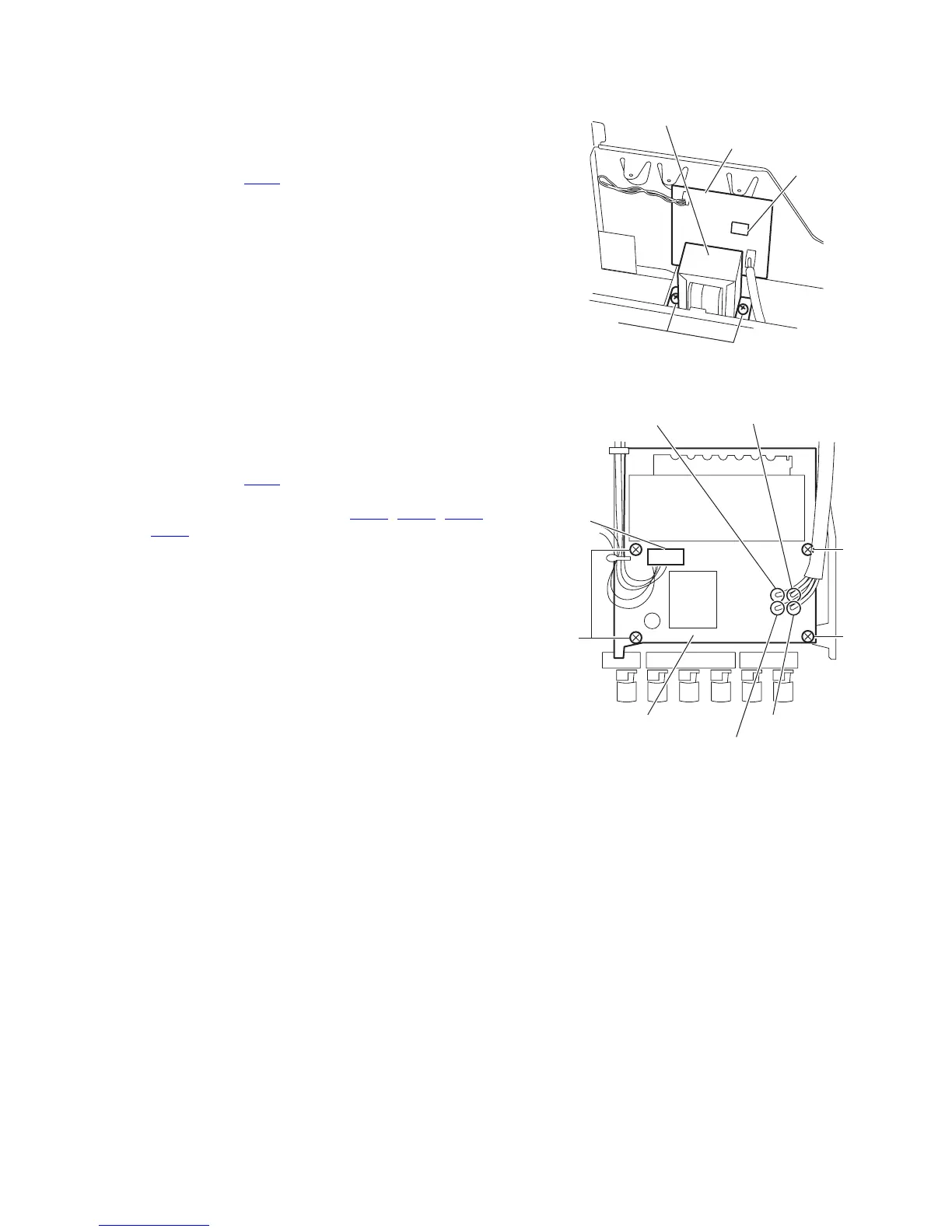
3.1.18 Removing the power/ fuse board
(See Fig.23)
• Prior to performing the following procedure, remove the top
cover, side panels, stay bkt, rear panel, regulator board and
power transformer 2.
(1) From the top side of the main body, disconnect the wire
from the connector CN25
on the power/ fuse board.
(2) Remove the four screws V attaching the power/ fuse board.
(3) Remove the solder from the points PW21
, PW22, PW23
and PW24 on the power/ fuse board.
Fig.23
Power 1 board
CN41
U
Power transformer 3
V
PW23 (red)
PW21 (blue)
PW22 (brown)
PW24 (white)
CN25
Power/ fuse board
 Loading...