1-10 (No.MB177)
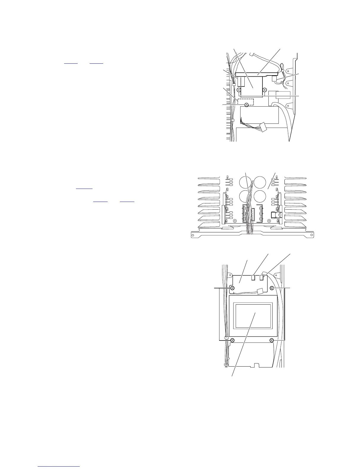
3.1.14 Removing the power transformer 1 with the power 2 board
(See Fig.19)
• Prior to performing the following procedure, remove the top
cover, side panels, stay bkt and regulator board.
(1) From top side of the main body, disconnect the wire from
the connector CN46
and CN47 on the power 2 board.
(2) Remove the two screws R attaching the power transformer
1.
3.1.15 Removing the thermal SW 1 board
(See Fig.19)
• Prior to performing the following procedure, the top cover, side
panels, stay bkt and regulator board.
(1) From top side of the main body, remove the screw S
attaching the thermal SW 1 board.
Fig.19
3.1.16 Removing the power transformer 2
(See Figs.20 and 21)
• Prior to performing the following procedure, remove the top
cover, side panels, stay bkt and regulator board.
(1) From the top side of the main body, disconnect the wire
from the connector CN701
on the power amp. board. (See
fig.20)
(2) Remove the solder points PW81 and PW82 on the power
trans 1 board. (See fig.21)
(3) Remove the four screws T attaching the power transformer
2. (See fig.21)
Fig.20
Fig.21
S
Power 2 board
CN47
CN46
R
Power transformer 1
Thermal SW
1 board
Power amp. boardCN701
T
T
PW81 PW82
Power trans 1
board
Power transformer 2
 Loading...