(No.MB177)1-9
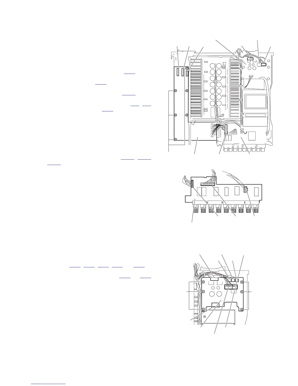
3.1.11 Removing the main board
(See Figs.16 and 17)
• Prior to performing the following procedure, remove the top
cover, rear panel, front panel assembly, Y/C separator board,
DSP 1 board, DSP 2 board, shield cover, audio signal 1 board,
audio signal 2 board, video board, S video board, component
video board and D5 video board.
(1) From the top side of the main body, cut off the tie bands
fixing the wire. (See fig.16)
(2) Disconnect the wire from the connector CN62
on the
regulator board. (See fig.16)
(3) Disconnect the wire from the CN44
on the power 2 board .
(See fig.16)
(4) Disconnect the wire from the connector CN743
on the
speaker relay board. (See fig.17)
(5) Disconnect the card wire from the connector CN1
, CN2
and the wire from the connector CN11 on the main board.
(See fig.16)
(6) Remove the seven screws P attaching the main board, and
take out the main board. (See fig.16)
3.1.12 Removing the speaker relay board
(See Fig.17)
• Prior to performing the following procedure, remove the top
cover, side panels, stay bkt and rear panel.
(1) Disconnect the wire from the connector CN741
, CN742
and CN743 on the speaker relay board.
Fig.16
Fig.17
3.1.13 Removing the regulator board
(See Fig.18)
• Prior to performing the following procedure, remove the top
cover, side panels and stay bkt.
(1) From top side of the main body, disconnect the wires from
the connectors CN61
, CN62, CN63, CN64 and CN65 on
the regulator board.
(2) Disconnect the wires from the connectors CN44
and CN45
on the power 2 board.
(3) Remove the six screws Q attaching the regulator board.
Reference:
When attaching the screw Q, attach the lug wire with it.
Fig.18
P
Regulator board
CN62
CN44
Power 2 board
CN2
CN743
Main board
CN1 CN11
Speaker relay board
CN743 CN742CN741
Speaker relay board
CN61
Regulator board
Q
CN45
CN44
Q
Power 2 boardCN63
CN65 CN64
CN62
 Loading...