(No.MB177)1-13
3.2 Power amp. assembly section
• Remove the power amp. assembly from the main body.
(See "Removing the power amp. assembly".)
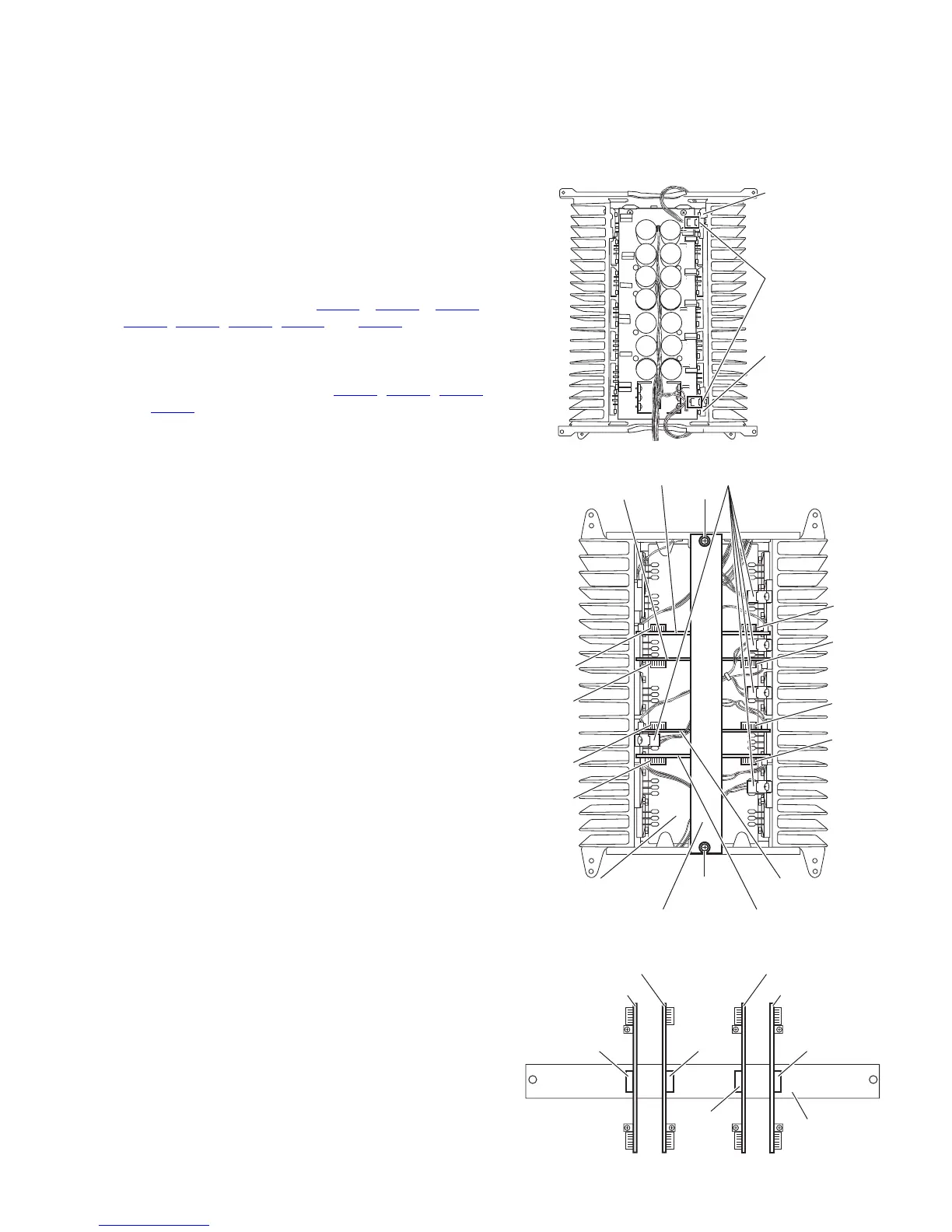
3.2.1 Removing the relay board & Rch amp. board & Lch amp. board & Cch amp. board & SL/SRch amp. board
(See Figs.1 to 3)
(1) From the top side of the amp. assembly, disconnect the
wires from the two connectors on each thermal
compensation board. (See fig.1)
(2) From the bottom side of the amp. assembly, remove the
two screws A attaching the relay board. (See fig.2)
(3) Disconnect the wires from the five connectors on each
thermal compensation board. (See fig.2)
(4) Disconecct the connectors CN712
, CN713, CN812,
CN813, CN772, CN773, CN752 and CN753 on the each
amp. board of Lch, Cch, SL/SRch and Rch from the power
amp. board. (See fig.2)
(5) From the top side of the relay board, disconnect the each
amp. board from the connectors CN721
, CN821, CN781
and CN761 on the relay board. (See fig.3)
Fig.1
Fig.2
Fig.3
Connectors
Thermal
compensation
board
Thermal
compensation
board
SL/SRch amp. board
Rch amp. board
Power amp. board
CN713
CN773
CN753
CN712
CN772
CN752
CN813
CN812
A
Relay board
A
ConnectorsLch amp. board
Cch amp. board
Relay board
SL/SRch amp. board
Rch amp. board
CN761CN821
CN781
Lch amp. board
Cch amp. board
CN721
 Loading...