1-16 (No.MB177)
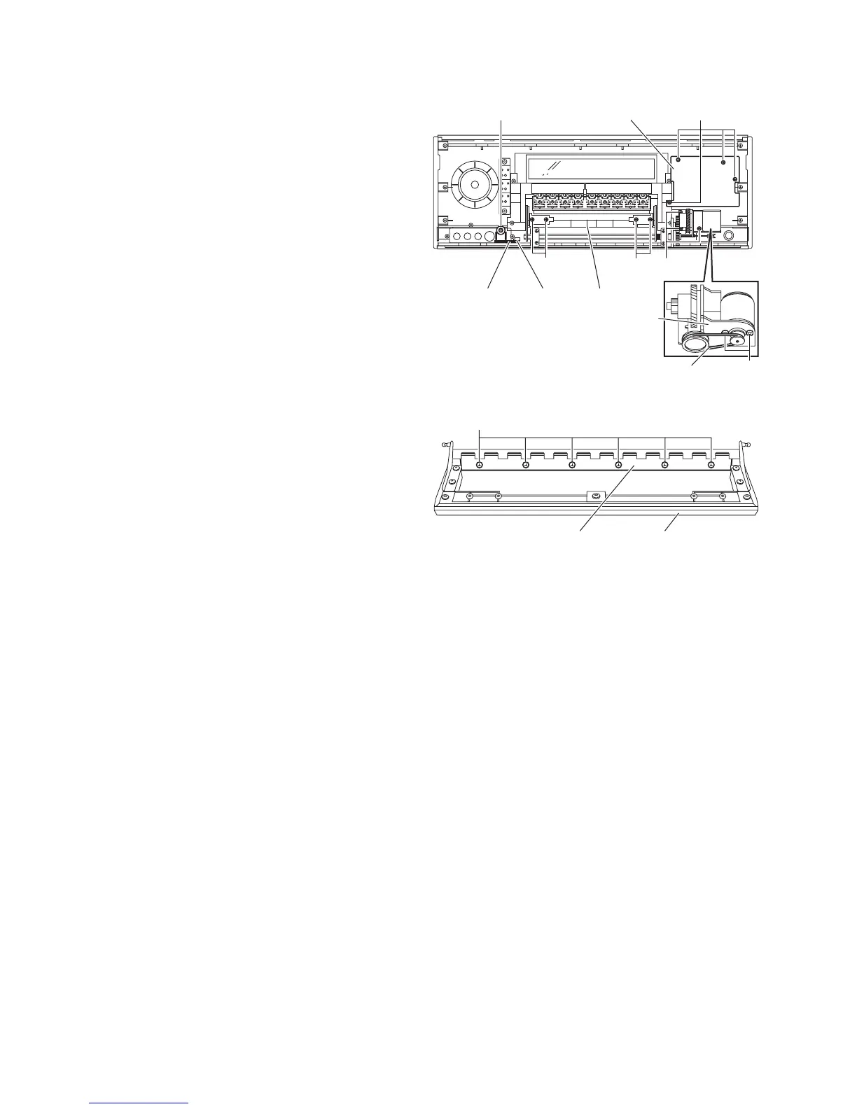
3.3.2 Removing the power switch board & front DIGITAL in board & motor assembly
(See Fig.3)
• Prior to performing the following procedure, remove the FL
display board.
(1) From the reverse side of the front panel assembly, remove
the four screws C attaching the power switch board and
take out the power switch board.
(2) Remove the screw D attaching the front DIGITAL in board
and take out the front DIGITAL in board.
(3) Remove the three screws E attaching the motor assembly
on the back of the front panel assembly.
(4) Remove the belt and the two screws F attaching the motor
assembly.
3.3.3 Removing the door input board
(See Figs.3 and 4)
• Prior to performing the following procedure, remove the FL
display board.
(1) From the reverse side of the front panel assembly, remove
the four screws G attaching the door and take out the door
to the forward. (See fig.3)
(2) From the reverse side of the door, remove the six screws
H attaching the door input board. (See fig.4)
Fig.3
Fig.4
F
Front DIGITAL
in board
DoorCN373
GG
E
Power switch board
C
D
Belt
Motor assembly
Door input board Door
H
 Loading...