(No.MB177)1-7
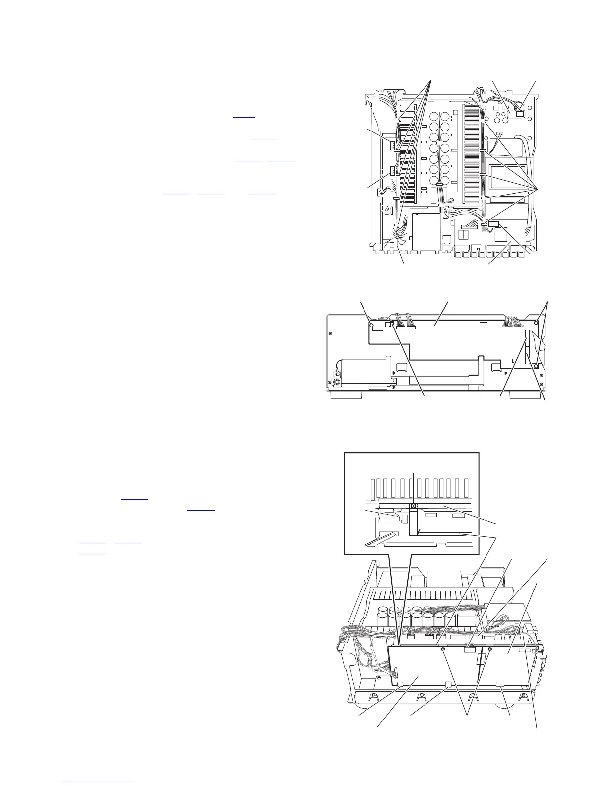
3.1.7 Removing the system control board
(See Figs.10 and 11)
• Prior to performing the following procedure, remove the top
cover, side panels, stay bkt and front panel assembly.
(1) From the top side of the main body, cut off the tie bands
fixing the wires. (See fig.10)
(2) Disconnect the wire from the connector CN45
on the power
2 board . (See fig.10)
(3) Disconnect the wire from the connector CN25
on the
power/ fuse board. (See fig.10)
(4) Disconnect the wire from the connector CN234
, CN208 on
the audio signal 1 board. (See fig.10)
(5) From the front side of the main body, disconnect the wires
from the connector CN963
, CN964 and CN981 on the
system control board. (See fig.11)
(6) Remove the three plastic rivet, and take out the system
control board. (See fig.11)
Fig.10
Fig.11
3.1.8 Removing the DSP 1 board & DSP 2 board & shield cover
(See Fig.12)
• Prior to performing the following procedure, remove the top
cover, side panels, stay bkt, front panel assembly and rear
panel.
(1) From the top side of the main body, disconnect the
connector CN631
on the DSP 2 board.
(2) Disconnect the connector CN203
on the audio signal 1
board, and cut off the tie bands fixing the wire.
(3) Remove the two plastic rivet, and disconnect the connector
CN633
, CN643 on the DSP 2 board, and disconnect
CN635 on the DSP 1 board.
(4) Remove the screw N attaching the barrier to the shield
cover, and take out the shield cover.
Fig.12
CN25
CN234
CN208
CN45
Power/ fuse boardAudio signal 1 board
Tie bands
Tie
bands
Power 2 board
System control board Plastic rivetPlastic rivet
CN963
CN981
CN964
Shield cover
(Top view)
CN631
CN635CN643 Plastic rivet
DSP 2 board
N
CN203
CN633
Audio signal 1 board
DSP 1
board
Barrier
 Loading...