1-8 (No.YD075)
SECTION 3
DISASSEMBLY
3.1 Removing the major parts
3.1.1 Destination of connectors
Destination of connectors
3.1.2 How to read the procedure table
This table shows the steps for disassembly of the externally fur-
nished parts and board assemblies. Reverse these steps when
re-assembling them.
(1) Order of steps in Procedure
When reassembling, perform the step(s) in the reverse or-
der.
These numbers are also used as the identification (loca-
tion) No. of parts Figures.
(2) Part name to be removed or installed.
(3) Fig. No. showing procedure or part location.
(4) Identification of part to be removed, unhooked, unlocked,
released, unplugged, unclamped or unsoldered.
P= Spring, W= Washer, S= Screw, L= Locking tab, SD=
Solder, CN**(WR**)= Remove the wire (WR**) from the
connector (CN**).
Note:
• The bracketed ( ) WR of the connector symbol are
assigned nos. in priority order and do not corre-
spond to those on the spare parts list.
(5) Adjustment information for installation
3.1.3 Disassembly procedure
<Note 2a>
• Be careful not to damage the connector and wire etc. during
connection and disconnection.
• When connecting the flat wire to the connector, be careful with
the flat wire direction.
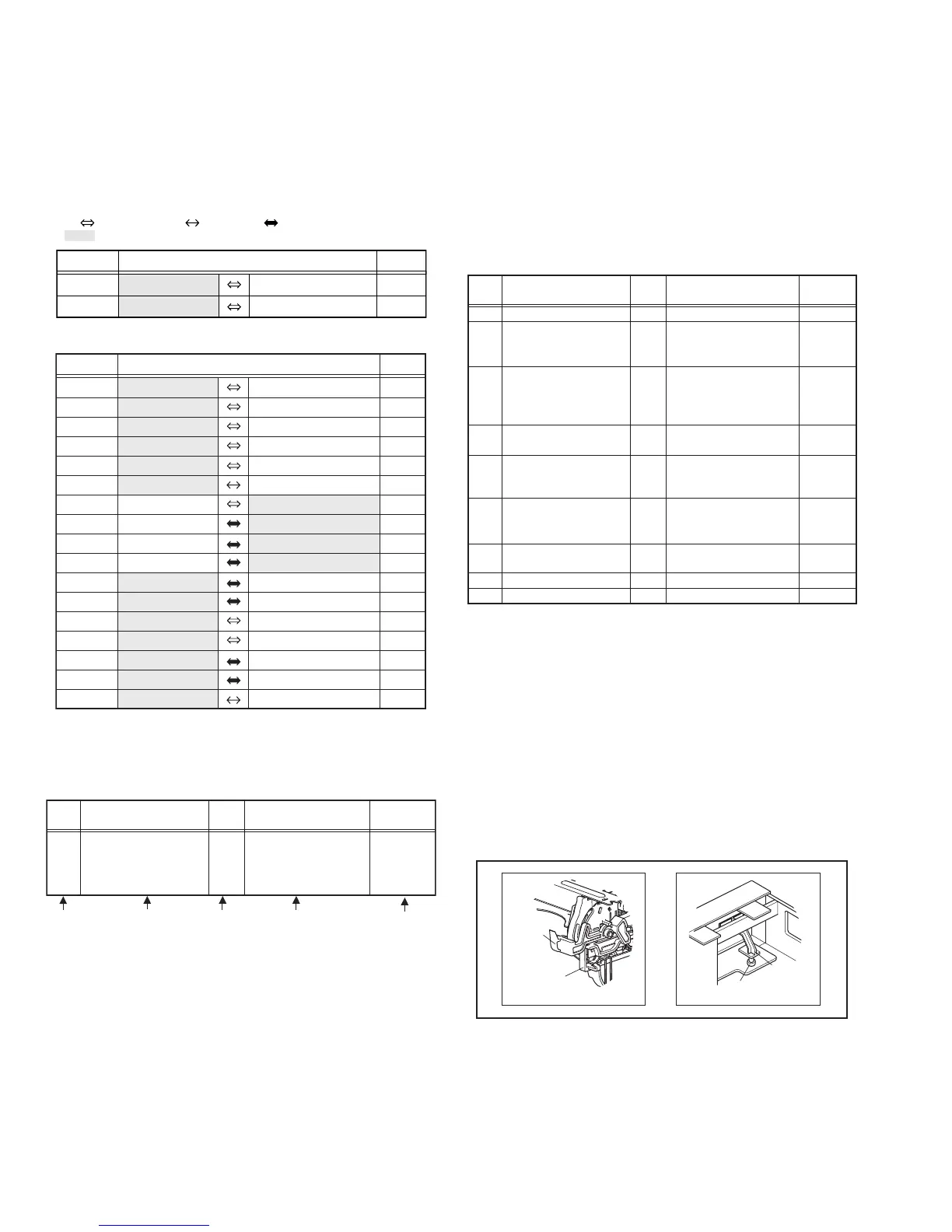
<Note 2b>
• When reattaching the Front panel assembly, make sure that
the door opener of the Side frame (R) is lowered in position pri-
or to the reinstallation.
• When reattaching the Front panel assembly, pay careful attention
to the switch lever of the Front panel assembly not to make it
touch the switch knob of the Main board assembly from the side.
• When reattaching the Front panel assembly, lift the Cassette
door slightly.
Fig.3-1a
<Note 3a>
• When reattaching the Mechanism assembly, secure the
screws (S3a to S3b) in the order of 1,2,3.
• When reattaching the Mechanism assembly, be sure to align
the phase of the Rotary encoder on the Main board assembly.
• When reattaching the Mechanism assembly, set the “Mecha-
nism assembling mode”. [See “MECHANISM ASSEMBLY
SERVICE MANUAL (No. 86700)”.]
WR2a
WR2b
Main CN101
Main CN103
40
10
CONN. No. PIN No.CONNECTOR
Two kinds of double-arrows in connection tables respectively
show kinds of connector/wires.
: The connector of the side to remove
: Wire: Flat wire : Board to board (B-B)
Digital CN761
Digital CN762
CONN. No. PIN No.CONNECTOR
WR2a
WR2b
WR3a
WR3b
WR4a
WR4b
WR5a
WR5b
WR5c
WR5d
WR6a
WR6b
WR6c
WR6d
WR6e
WR7a
WR7b
Main
Main
Main
Drum assembly
DVD unit
DVD unit
Junction
Junction
Junction
Junction
Main
Main
Junction
Junction
SW.REG
SW.REG
SW.REG
CN3104
CN3102
CN2001
CN7110
CN7109
CN7108
CN7121
CN3103
CN2601
CN7123
CN7107
CN5304
CN5301
CN5302
Switch/jack
Display/switch
A/C head
Main
Digital
Junction
Digital
Digital
Digital
Digital
Junction
Junction
Main
Main
Junction
Main
Fun motor
CN7201
CN7001
CN1
CN2201
CN5503
CN1103
CN1102
CN1101
CN1801
CN7102
CN8001
CN501
CN7111
CN5501
CN5311
9
15
6
9
40
4
17
15
15
9
19
11
4
13
19
19
2
(1) (2) (3) (4) (5)
Step/
Loc No.
Part Name
Fig.
No.
Point Note
[1] Top cover 3-1a
4(S1a),(S1b),3(L1a), <Note 1a>
2(SD1a),(P1a),(W1a),
CN1(WR1a),
Bracket 2(S1c)
----------------------------------------
Step/
Loc No.
Part Name
No.
Fig.
Point Note
Top cover
Front panel assembly
(Switch/jack board assembly)
(Display/switch board assembly)
Mechanism assembly
(Drum assembly)
DVD unit
(Bracket)
Digital board assembly
(Shield cover)
Junction board assembly
Switching regulator board assembly
Rear cover
Main board assembly
3-1d
3-1a,
3-1d
3-1b,
3-1c,
3-1d
3-1d
3-1d
3-1d
3-1d
3-1d
3-1d
6(S1a)
(S2a),(S2b),3(L2a),5(L2b)
CN3104(WR2a),
CN3102(WR2b),(WR2c),(WR2d)
CN2001(WR3a),
3(S3a)
CN(WR3b)
(S3c),(S3d),(S3e)
4(S4a),4(S4b)
(WR4a),(WR4b)
4(S5a),4(S5b)
CN7100(WR5a),CN1102(WR5b),
CN1101(WR5c),CN1801(WR5d)
(S6a),CN3103(WR6a),
CN2601(WR6b),CN7123(WR6c),
CN7107(WR6d),CN5304(WR6e)
4(S7a),CN5301(WR7a),
CN5302(WR7b)
2(S8a),7(S8b),(S8c),3(L8a)
2(S9a)
<Note2a>
<Note2b>
<Note2a>
<Note3a>
<Note3b>
<Note3c>
<Note2a>
<Note2a>
<Note2a>
<Note2a>
[1]
[2]
[3]
[4]
[5]
[6]
[7]
[8]
[9]
Door
opener
Side
frame(R)
Switch
knob
Switch
lever
 Loading...