(No.MB616<Rev.002>)1-29
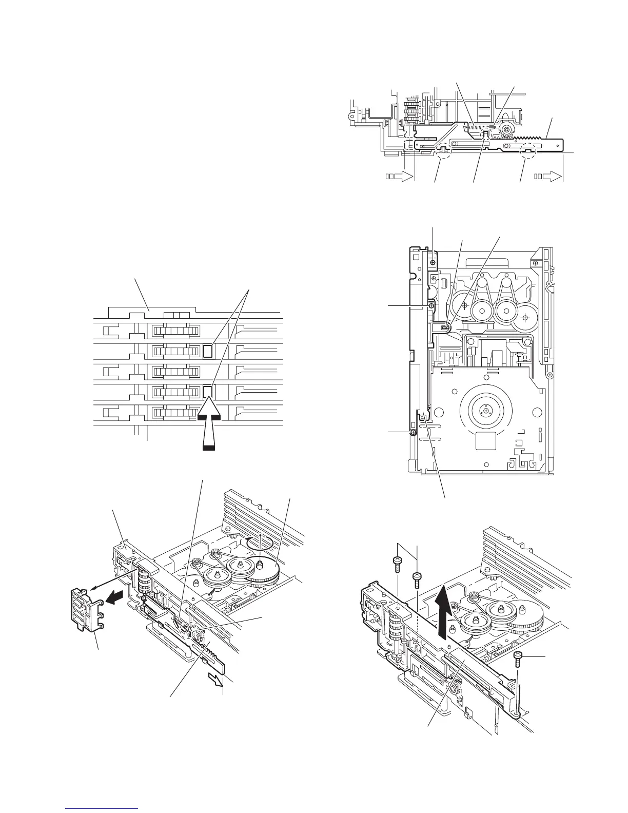
3.2.12 Removing the side (R) assembly
(See Fig.23 to 27)
• Remove the tray assemblies and DVD servo board.
(1) From the inside of the side (R) assembly, release the two
tabs aa of the gear cover and remove the gear cover out-
ward. (See Figs.23 and 24.)
(2) From the right side of the DVD changer mechanism as-
sembly, remove the elevator spring attached to the hook
ab of the loader assembly. (See Figs.24 and 25.)
(3) From the top side of the DVD changer mechanism assem-
bly, turn the gear 1 clockwise to move the elevator cam
rearward. (See Fig.25.)
(4) Move the two slots ac and joint ad of the elevator cam and
remove the elevator cam outward. (See Fig.25.)
(5) Remove the three screws P and detaches the side (R) as-
sembly upward. (See Figs.26 and 27.)
Note:
When reattaching the side (R) assembly, make sure to fit the
shaft (part ae) into the slot of the select lever. (See Fig.26.)
Fig.23
Fig.24
Fig.25
Fig.26
Fig.27
aa
Side(R) assembly
Side(R) assembly
Elevator spring
Gear cover
ab
Gear 1
Loader assembly
Elevator cam
Elevator spring
ab
ac
acad
P
Side(R) assembly
P
P
ae
Select lever
Side(R) assembly
P
P