- 9 -
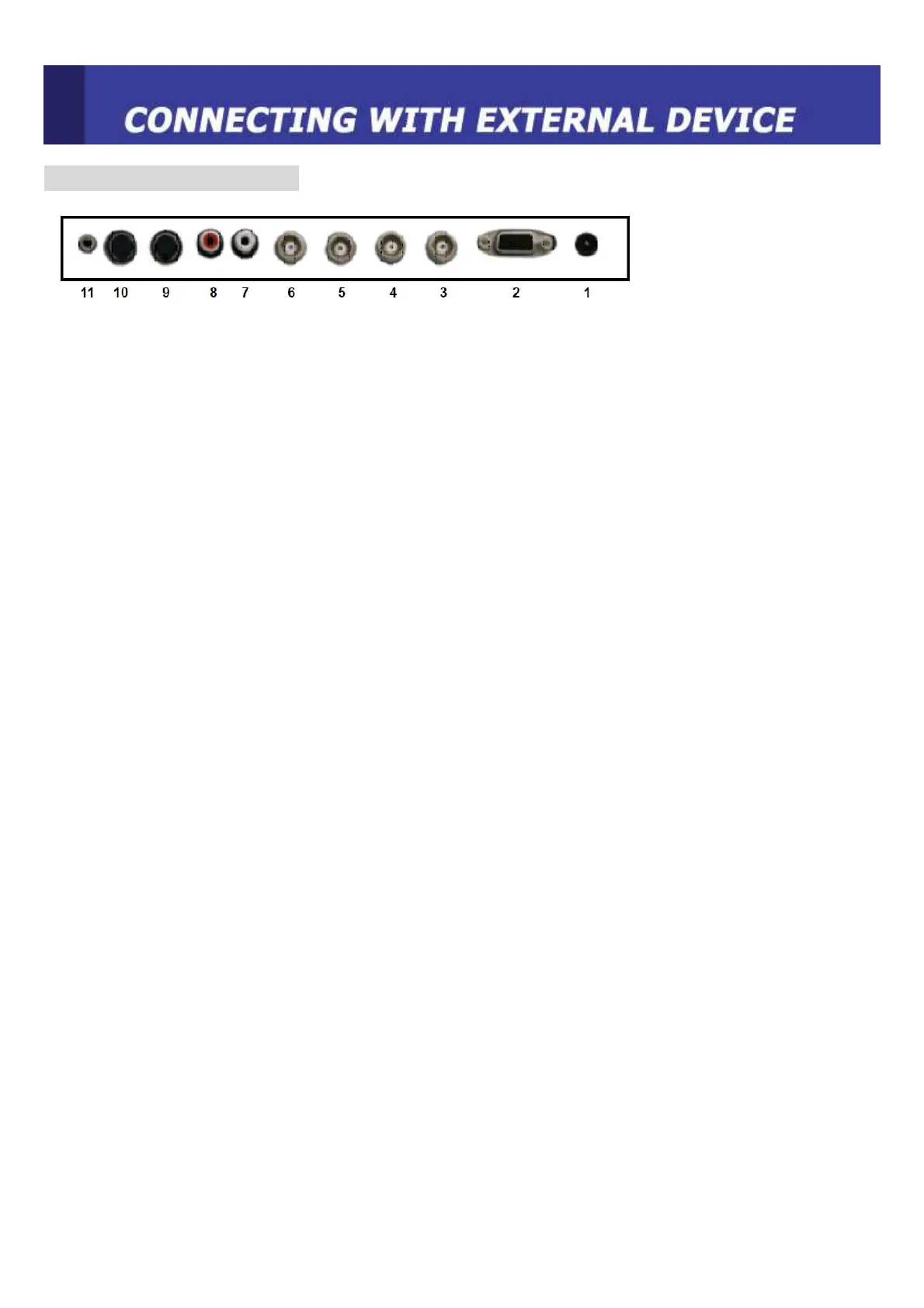
REAR PANEL CONTROL
1. DC 12V Power IN
2. RGB IN
RGB signal input
3. VIDEO 1(AV1) IN
Composite signal input for AV1
4. VIDEO 1(AV1) OUT
Composite looping output for AV1
5. VIDEO 2(AV2) IN
Composite signal input for AV2
6. VIDEO 2(AV2) OUT
Composite looping output for AV2
7, AUDIO L IN
Left side audio signal input. This input is for AV1, AV2, S-VIDEO
8. AUDIO R IN
Right side audio signal input. This input is for AV1, AV2, S-VIDEO
9. S-VIDEO (Y/C) IN
Y/C separated signal input
10. S-VIDEO (Y/C) OUT
Y/C separated signal looping output
11. PC STEREO IN
Note: When doing Looping out connection by more than 3, please use distributor.
 Loading...