EasyManua.ls Logo

JVC GR-D60EK - User Manual

JVC GR-D60EK
88 pages
To Next Page IconTo Next Page
Loading...
SERVICE MANUAL
COPYRIGHT © 2003 VICTOR COMPANY OF JAPAN, LTD.
No.86732
2003/04
DIGITAL VIDEO CAMERA
86732200304
GR-D60EK,GR-D60EX,GR-D60EY
SPECIFICATION
Camcorder
General
Digital Video Camera
Digital Still Camera Function
Connectors
AC Adapter
Regarding service information other than these sections, refer to the service manual No. 86733 (GR-D70EX).
A
lso, be sure to note important safety precautions provided in the service manual.
For disassembling and assembling of MECHANISM ASSEMBLY, refer to the SERVICE MANUAL No.86700 (MECHANISM ASSEMBLY).
PAL
Power supply : DC 11.0 V (Using AC Adapter)
DC 7.2 V (Using battery pack)
Power consumption
LCD monitor off,
viewfinder on : Approx. 3.4 W
LCD monitor on,
viewfinder off : Approx. 4.7 W
Dimensions
(W x H x D) : 69 mm x 94 mm x 143 mm
(with the LCD monitor closed and the viewfinder pushed
back in)
Weight : Approx. 525 g
Operating temperature : 0°C to 40°C
Operating humidity : 35% to 80%
Storage temperature : -20°C to 50°C
Pickup : 1/6" CCD
Lens : F 1.6, f = 2.7 mm to 43.2 mm, 16:1 power zoom lens
Filter diameter : Ø37 mm
LCD monitor : 2.5" diagonally measured, LCD panel/TFT active
matrix system
Viewfinder : Electronic viewfinder with 0.24" black/white LCD
Speaker : Monaural
Format : DV format (SD mode)
Signal format : PAL standard
Recording/Playback format : Video: Digital component recording
: Audio: PCM digital recording,
32 kHz 4-channel (12-bit),
48 kHz 2-channel (16-bit)
Cassette : Mini DV cassette
Tape speed : SP : 18.8 mm/s
LP : 12.5 mm/s
Maximum recording time : SP : 80 min.
(using 80 min. cassette) LP : 120 min.
Storage media : SD Memory Card/MultiMediaCard
Compression system : JPEG (compatible)
File size : 2 modes (1024 x 768 pixels, 640 x 480 pixels)
Picture quality : 2 modes (FINE/STANDARD)
Approximate number of
storable images : pg. 18.
S-Video
Output : Y : 1 V (p-p), 75 , analogue
C : 0.29 V (p-p), 75 , analogue
Input* : Y : 0.8 V (p-p) -1.2 V (p-p), 75 , analogue
C : 0.2 V (p-p) -0.4 V (p-p), 75 , analogue
AV
Video output : 1 V (p-p), 75 , analogue
Video input* : 0.8 V (p-p) -1.2 V (p-p), 75 , analogue
Audio output : 300 mV (rms), 1 k, analogue, stereo
Audio input* : 300 mV (rms), 50 k, analogue, stereo
DV
Output : 4-pin, IEEE 1394 compliant
Input : 4-pin, IEEE 1394 compliant
USB* :5-pin
EDIT : Ø3.5 mm, 2-pole
* GR-D70 only
Power requirement : AC 110 V to 240 V ~, 50 Hz/60 Hz
Output : DC 11 V , 1 A
Specifications shown are for SP mode unless otherwise indicated. E & O.E. Design and specifications subject
to change without notice.
GR-D60EK,GR-D60EX,GR-D60EY M3D126

Table of Contents

Question and Answer IconNeed help?

Do you have a question about the JVC GR-D60EK and is the answer not in the manual?

JVC GR-D60EK Specifications

General IconGeneral
TypeMini DV
Recording MediaMiniDV
Sensor TypeCCD
Optical Sensor Size1/6 inch
Optical Zoom16x
Digital Zoom800x
Screen Size2.5 inch
Image StabilizerElectronic
Audio Recording FormatPCM
Battery TypeLithium-ion
Effective Pixels680, 000
ViewfinderColor
Video Recording FormatDV
InterfaceIEEE 1394 (FireWire)
Battery LifeApprox. 90 minutes

Summary

SPECIFICATION

General

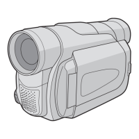
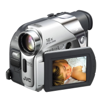
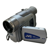
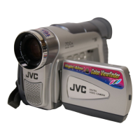
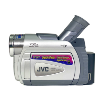
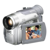
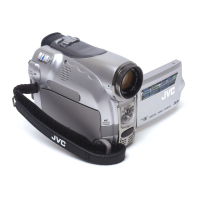
Overall technical specifications for the camcorder and digital still camera functions.

Digital Still Camera Function

Details on storage media, compression, file size, and picture quality.

Connectors

List of available input/output connectors and their specifications.

SECTION 1 PRECAUTIONS

1.1 SAFTY PRECAUTIONS

Essential safety guidelines and warnings for servicing the product.

1.1.1 Precautions during Servicing

Essential safety guidelines and warnings for servicing the product.

1.1.2 Safety Check after Servicing

Insulation resistance test

Procedure to verify safe electrical insulation levels after repair.

Leakage current test

Method to measure and ensure low leakage current for user safety.

SECTION 2 SPECIFIC SERVICE INSTRUCTIONS

2.1 BEFORE ASSEMBLY AND DISASSEMBLY

General safety and handling precautions before starting disassembly.

2.1.1 Precautions

General safety and handling precautions before starting disassembly.

2.1.2 Assembly and disassembly

Step-by-step procedures for disassembling and reassembling unit parts.

2.2 ASSEMBLY AND DISASSEMBLY OF CABINET PARTS

Procedures for disassembling and reassembling the external cabinet parts.

2.2.1 Disassembly flow chart

Visual guide for the sequence of cabinet part disassembly.

2.3 ASSEMBLY AND DISASSEMBLY OF CAMERA SECTION AND BOARD ASSEMBLY

2.3.1 Disassembly flow chart

Flowchart for disassembling camera sections and board assemblies.

2.4 ASSEMBLY AND DISASSEMBLY OF [8]VF ASSEMBLY

2.4.1 Disassembly of VF ASSEMBLY

Specific steps for disassembling the Viewfinder (VF) assembly.

2.5 ASSEMBLY AND DISASSEMBLY OF [10] MONITOR ASSEMBLY (CABINET PARTS)

2.5.1 Disassembly of MONITOR ASSEMBLY (2.5 INCH)

Procedure for disassembling the 2.5-inch monitor assembly.

2.5.2 Disassembly of MONITOR ASSEMBLY (3.5 INCH)

2.6 ASSEMBLY AND DISASSEMBLY OF [2]OP BLOCK ASSEMBLY; CCD BOARD ASSEMBLY (CAMERA SECTION AND BOARD ASSEMBLY)

2.6.1 Precautions

Handling precautions for CCD sensor, LPF, and lenses during service.

2.6.2 Disassembly of CCD BOARD ASSEMBLY and CCD BASE ASSEMBLY

Steps for removing the CCD board and base assemblies.

2.8 TAKE OUT CASSETTE TAPE

2.9 EMERGENCY DISPLAY

SECTION 3 ADJUSTMENT

3.1 PREPARATION

General preparation steps and precautions before performing adjustments.

3.2 TOOLS REQUIRED FOR ADJUSTMENT

List of specialized tools needed for calibration and adjustment procedures.

3.5 ELECTRICAL ADJUSTMENT

3.5.1 Electrical adjustment with personal computer

Guide for performing electrical adjustments using a PC and service support system.

SCHEMATIC DIAGRAMS

MAIN IF SCHEMATIC DIAGRAM

Schematic showing the main Intermediate Frequency (IF) circuit.

CPU SCHEMATIC DIAGRAM

Schematic illustrating the Central Processing Unit (CPU) circuit connections.

AUDIO SCHEMATIC DIAGRAM

Schematic detailing the audio processing circuits.

DV_MAIN SCHEMATIC DIAGRAM

Schematic for the main Digital Video (DV) processing section.

CHARTS AND DIAGRAMS

NOTES OF SCHEMATIC DIAGRAM

Explanations of symbols, units, and notations used in schematic diagrams.

4. Voltage measurement

Guidelines for measuring voltages in various circuits for diagnostics.

PARTS LIST

1. EXPLODED VIEW

Diagrams showing how parts fit together for product assembly.

1.1 PACKING AND ACCESSORY ASSEMBLY <M1>

Diagram and list of packing materials and accessories included with the product.

1.2 FINAL ASSEMBLY <M2>

1.3 MECHANISM ASSEMBLY <M3>

1.4 ELECTRONIC VIEWFINDER ASSEMBLY <M4>

1.5 MONITOR ASSEMBLY (2.5 INCH) <M5>

2. PARTS LIST

PACKING AND ACCESSORY ASSEMBLY <M1>

List of parts for packing and accessories, organized by model.

FINAL ASSEMBLY <M2>

Comprehensive parts list for the final product assembly.

MECHANISM ASSEMBLY <M3>

Detailed parts list for the mechanism assembly.

ELECTRONIC VIEWFINDER ASSEMBLY <M4>

Detailed parts list for the electronic viewfinder assembly.

MAIN BOARD ASSEMBLY <01>

BL-2.5 BOARD ASSEMBLY <03>

CCD BOARD ASSEMBLY <04>

PREMDA BOARD ASSEMBLY <05>

JACK BOARD ASSEMBLY <06>

B;W-VF BOARD ASSEMBLY <07>

Related product manuals