(No.YF139)1-13
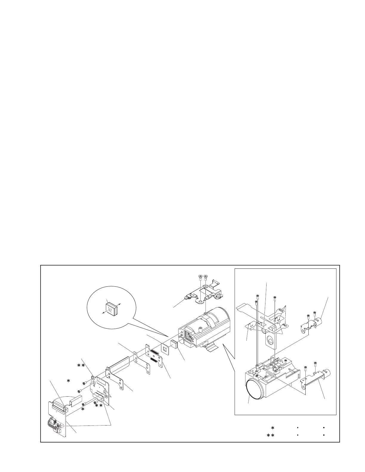
3.2.4 ASSEMBLY/DISASSEMBLY OF [20] OP BLOCK ASSEMBLY/CCD BOARD ASSEMBLY
zPrecautions
(1) Take care in handling the CCD IMAGE SENSOR, OPTICAL
LPF and lens components when performing maintenance
etc., especially with regard to surface contamination, at-
tached dust or scratching. If fingerprints are present on
the surface they should be wiped away using either a sil-
icon paper, clean chamois or the cleaning cloth.
(2) The CCD IMAGE SENSOR may have been shipped with
a protective sheet attached to the transmitting glass.
When replacing the CCD IMAGE SENSOR, do not peel
off this sheet from the new part until immediately before
it is mounted in the OP BLOCK ASSEMBLY.
(3) As the attachment direction of the OPTICAL LPF is im-
portant, be careful when removing it. Make sure to reat-
tach the OPTICAL LPF in its original direction.
zDisassembly of OP BLOCK ASSEMBLY / CCD BOARD AS-
SEMBLY
(1) Remove the two screws (1, 2), and then remove the BKT
(OP) ASSY.
(2) Be careful in handling the SPACER and the CONNEC-
TOR that connects the CDS BOARD ASSY and the CCD
BOARD ASSY. Remove the CDS BOARD ASSY by pull-
ing it parallel to the CCD BOARD ASSY.
(3) Remove the two screws (3, 4), and then remove the CCD
BOARD ASSY, SHIELD (CCD), HEAT SHEET (CCD),
and the CCD BASE ASSY.
NOTE20a:
Be careful in handling as there are only the OPTICAL
LPF and the SHEET stored inside the OP BLOCK
ASSY when the CCD BASE ASSY is removed.
(4) Remove the SHEET and the OPTICAL LPF.
(5) Unsolder the 24 solder points (SD20a), remove the two
screws (5, 6), and then remove the CCD BASE ASSY.
NOTE20b:
Replace the CCD image sensor as a whole unit of CCD
BASE ASSY instead of replacing it as a single part.
(6) Detach the HEAT SHEET (CCD), and remove the
SHIELD (CCD) from the CCD BOARD ASSY.
zAssembly of OP BLOCK ASSEMBLY / CCD BOARD AS-
SEMBLY
(1) Set the SHIELD (CCD) first, then the HEAT SHEET
(CCD), and then the CCD BASE ASSY to the CCD
BOARD ASSY, and tighten them with the screws (5, 6).
(2) Solder the 24 solder points (SD20a) on the CCD BOARD
ASSY.
(3) Set the OPTICAL LPF first, and then the SHEET to the
OP BLOCK ASSEMBLY.
NOTE20c:
When attaching the OPTICAL LPF, be careful with the
attachment direction to avoid any uplift or unevenness
for the sheet attachment.
(4) Attach the CCD BOARD ASSY (CCD BASE ASSY and
others), and then tighten them with the two screws (3, 4).
zReplacement of service repair parts
The service repair parts for the OP BLOCK ASSEMBLY are as
listed below.Take special care not to disconnect any of the FPC
wires or cause any damage due to soldering (excessive heating).
(1) FOCUS MOTOR UNIT
(2) ZOOM MOTOR UNIT
(3) AUTO IRIS UNIT
NOTE20d:
When replacing the FOCUS MOTOR UNIT or the ZOOM
MOTOR UNIT, solder the FPC at a space of about 0.5 mm
above the terminal pin.
NOTE20e:
The AUTO IRIS UNIT includes the FPC ASSEMBLY and
two sensors.
Fig.3-2-4
CCD PWB ASSY
CCD BASE ASSY
1
(S20a)
5
(S20c)
3
(S20b)
4
(S20b)
6
(S20c)
7
(S20d)
8
(S20d)
9
(S20d)
11
(S20d)
12
(S20d)
13
(S20d)
SD20b
SD20b
10
(S20d)
CN20
SD20a
2
(S20a)
CDS PWB ASSY
SPACER
CONNECTOR
HEAT SHEET
(CCD)
BKT(OP) ASSY
OP BLOCK ASSY
SHET
OPTICAL LPF
SHIELD(CCD)
FOCUS MOTOR
UNIT
SENSOR
AUTO IRIS UNIT
ZOOM MOTOR UNIT
: 0.118N m(1.2kgf cm)
: 0.147N m(1.5kgf cm)
OP
side
CCD
side
blue
NOTE20a,c
NOTE20a
NOTE20d
NOTE20e
NOTE20d

 Loading...