1-14 (No.YF139)
SECTION 4
ADJUSTMENT
4.1 PREPARATION
4.1.1 Precaution
Camera system and deck system of this model are specially
adjusted by using PC.
However, if parts such as the following are replaced, an
adjustment is required. The adjustment must be performed in a
Service Center equipped with the concerned facilities.
• OP BLOCK ASSEMBLY
• MONITOR ASSEMBLY
• EEP ROM (IC4502 of MAIN board)
In the event of malfunction with electrical circuits, first find a
defective portion with the aid of proper test instruments as shown
in the following electrical adjustment procedure, and then
commence necessary repair/ replacement/adjustment.
• In observing chip TP, use IC clips, etc. to avoid any stress.
Prior to replacement of chip parts (especially IC), remove the
solder completely to prevent peeling of the pattern.
• Use a patch cord if necessary. As for a patch cord, see the
BOARD INTERCONNECTIONS.
• Since connectors are fragile, carefully handle them in
disconnecting and connecting the FPC.
4.1.2 REQUIRED TEST EQUIPMENT
• Personal computer (for Windows)
• Color TV monitor
• Oscilloscope (dual-trace type, observable 100MHz or higher
frequency). The one observable 300 MHz or higher frequency
is recommended.
• Digital voltmeter
• DC power supply or AC adapter
• Frequency counter (with threshold level adjuster)
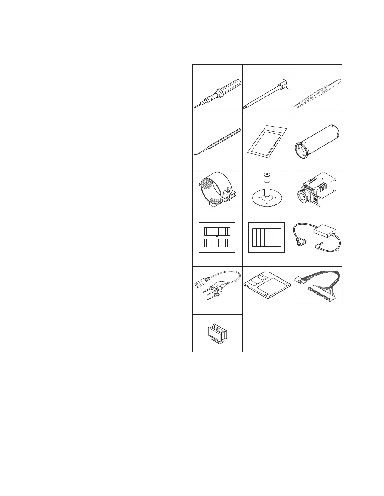
4.1.3 TOOLS REQUIRED FOR ADJUSTMENT
• Torque driver
Be sure to use to fastening the mechanism and exterior parts
because those parts must strictly be controlled for tightening
torque.
• Bit
This bit is slightly longer than those set in conventional torque
drivers.
• Tweezers
To be used for removing and installing parts and wires.
• Chip IC replacement jig
To be used for adjustment of the camera system.
• Cleaning cloth
Recommended the Cleaning cloth to wipe down the video
heads, mechanism (tape transport system), optical lens sur-
face.
Service Support System
YTU94057-95
INF Adjustment Lens
YTU92001B
INF Adjustment Lens Holder
YTU94087
Mini Stand
YTU93108
Light box Assembly
YTU93096A
Gray Scale Chart
YTU94133A
Color Bar Chart
YTU94133C
Communication Cable
YTU93107B
Conversion Connector
YTU94145L-30
PC Cable
QAM0099-005
Torque Driver
YTU94088
Bit
YTU94088-003
Chip IC Replacement Jig
PTS40844-2
Tweezers
P-895
Cleaning Cloth
KSMM-01
Jig Connector Cable
YTU93106A
 Loading...