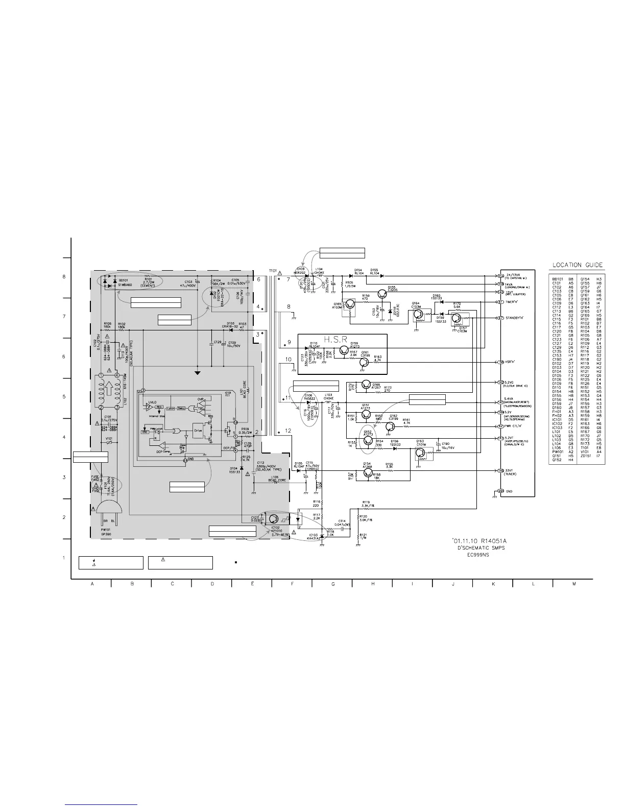
NOTES) Symbol denotes AC ground.
NOTES) Symbol denotes DC chassis ground.
NOTE) Warning
NOTE) Parts that are shaded are critical
NOTE) With respect to risk of fire or
NOTE) electricial shock.
BD101, R101 are defective.
Power dead.
F101 is defective.
Power dead.
IC101 is defective.
Switching dead.
D102 is defective.
No power.
D106 is defective.
No 5.3VA and 5VG, 5VT.
No 14VA, 12VA are 12VT.
D109, C120 are defective.
Q152 is defective.
No 5.2VT.
IC102, IC103 are defective.
Power dead.
NOTE :
1. Shaded( ) parts are critical for safety. Replace only
with specified part number.
2. Voltages are DC-measured with a digital voltmeter
during TUNER mode.