3-2
ELECTRICAL ADJUSTMENT PROCEDURES
1. Servo Adjustment
1) PG Adjustment
• Test Equipment
• Adjustment And Specification
a) OSCILLOSCOPE
b) PAL TEST TAPE (VHS SP)
c) JIG REMOCON (AUTO PG SETTING)
MODE
PLAY
• Adjustment Procedure
a) Insert the PAL SP Test Tape and play.
Note - Adjust the distance of X, pressing the Tracking(+) or Tracking(-) when the “ATR(OSD on moni-
tor)” is blink after PAL SP test Tape is inserted.
b) Press the Auto PG KEY on JIG Remocon(1’st) or Press “Play” key on set and “0” key on
Remocon.(Then check the light 4 Dot LED on CLK/LED - TRK is a Initial)
c) Press the Auto PG Key on JIG Remocon again (2’nd) or press “Play” key on set and “0” key on
Remocon again.(Then check the blink 4 Dot LED - At regular 0.25sec internal, Then check blink “PG
waveform” on oscilloscope(MONO Model)).
• Check the PG
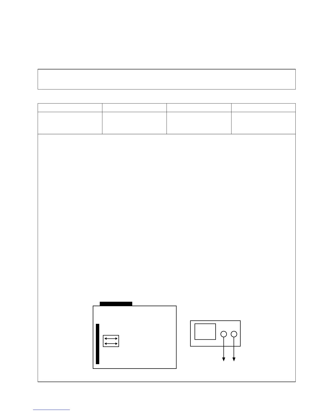
a) Connect the CH1 of the oscilloscope to the H/SW and CD2 to the Video out for the VCR.
b) Trigger the mixed Video Signal of CH2 to the CH1 H/SW(W501, W502), and then check the distance
(time difference), which is from the selected A(B) Head point of the H/SW(W501, W502) signal to the
starting point of the vertical synchronized signal, to 6.5H ± 0.5H (416µs, 1H=64.0µs).
• CONNECTION
V.Out
H/SW(W501, W502)
6.5 ± 0.5H
MEASUREMENT POINT ADJUSTMENT POINT SPECIFICATION