1-18 (No.YD002)
4.1.7 EVR Adjustment
Some of the electrical adjustments require the adjustment per-
formed by the EVR system. The main unit have EEPROMs for
storing the EVR adjustment data and user setups.
Notes:
• In the EVR adjustment mode, the value is varied with the
channel buttons (+, –). The adjusted data is stored when
the setting mode changes (from PB to STOP, when the
tape speed is changed, etc.). Take care to identify the
current mode of each adjustment item when making an
adjustment.
• When changing the address setting in the EVR adjust-
ment mode, use the Jig RCU or the remote controller
having numeric keypad with which a numeric code can
be directly input.
The remote control code of the Jig RCU corresponds to
each of the digit keys on the remote controller as fol-
lows.
• As the counter indication and remaining tape indication
are not displayed FDP during the EVR adjustment
mode, check them on the TV monitor screen.
• When performing the EVR adjustment, confirm that the
FDP indication is changed to the EVR mode, as shown
below.
Fig.4-1b EVR mode
4.2 Mechanism compatibility adjustment [VHS SECTION]
Notes:
• Although compatibility adjustment is very important, it
is not necessary to perform this as part of the normal
servicing work. It will be required when you have re-
placed the A/C head, drum assembly or any part of the
tape transport system.
• To prevent damaging the alignment tape in the compatibil-
ity adjustment, prepare a cassette tape (for self-recording/
playback), perform a test on it by transporting it and mak-
ing sure that the tape is not bent by the tape transport
mechanisms such as in the guide rollers.(See Fig.4-2b.)
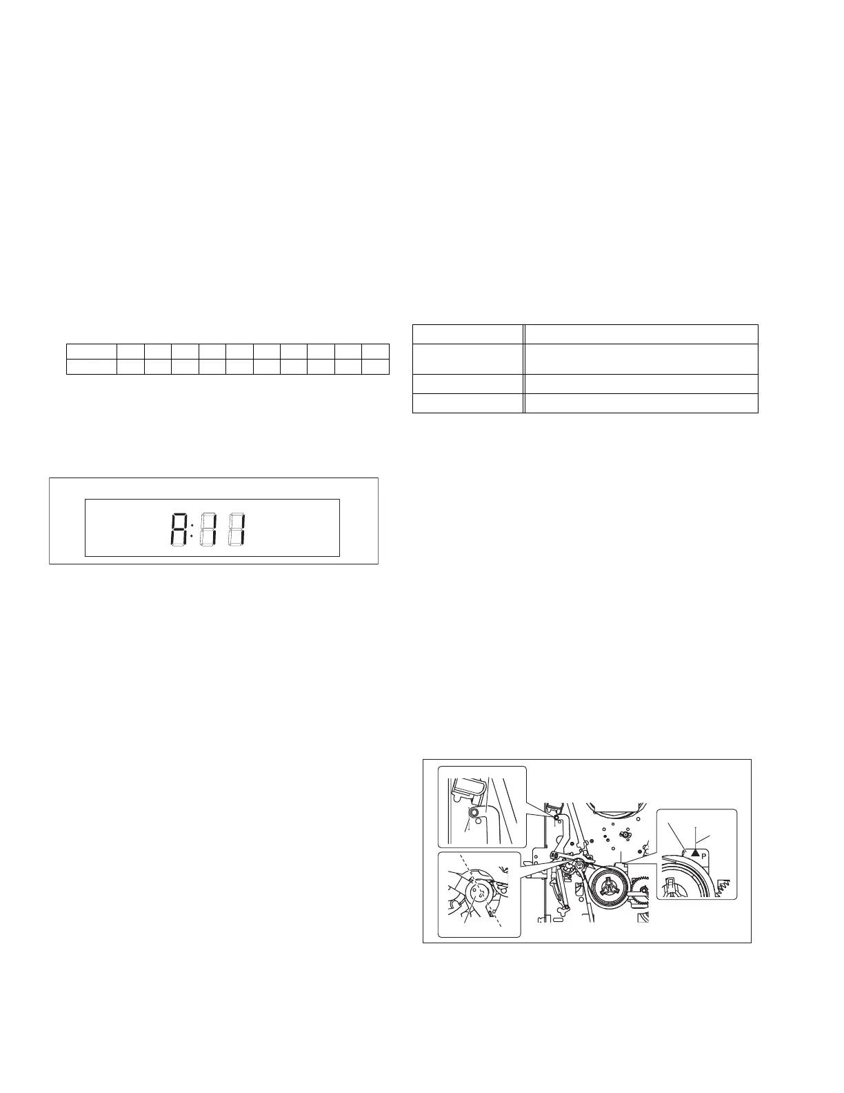
4.2.1 Tension pole position
Notes:
• This adjustment must be performed every time the ten-
sion band is replaced.
(1) Play back the back tension cassette gauge (A).
(2) Check that the indicated value on the left side gauge is
within the specified value (G).
(3) If the indicated value is not within the specified value (G),
perform the adjustment in a following procedure.(See
Fig.4-2a.)
a) Remove the top frame, cassette holder and side
frames (L/R) all together. (refer to the SERVICE
MANUAL No.86700 [MECHANISM ASSEMBLY].)
b) Rotate the loading motor gear to move the control
plate so that the triangular stamping to the left of the
“P”stamping is aligned with the stamping (a) on the
main deck. This positioning is mode (B1).
c) Adjust by turning the adjustment pin so that the tip of
the tension arm is aligned with the stamping (b) on
the main deck.
d) Rotate the reel disk (S) by about one turn clockwise
and make sure that the round hole of the adjustment
pin is located in the “OK” range. If it is outside this
range, restart the adjustment from the beginning.
After completion of the adjustment, rotate the loading gear
motor to return it to the mode (B2) position.
Fig.4-2a
Digit-key0123456789
Code 20 21 22 23 24 25 26 27 28 29
FDP
Signal (A) • Back tension cassette gauge [PUJ48076-2]
Mode (B1)
(B2)
•PB
• Eject end
Adjustment part (F) • Adjust pin [Mechansim assembly]
Specified value (G) • 25 - 51 gfcm (2.45 - 5 x 10
-
3
Nm)
OK
NG
ADJUST PIN
TENSION ARM
Stamping(b)
Stamping(a)
CONTROL PLATE
www.freeservicemanuals.info
Digitized in Heiloo Netherland
 Loading...