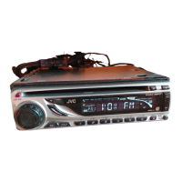
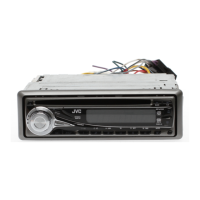
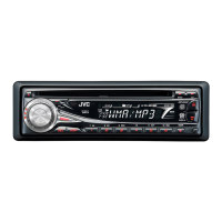
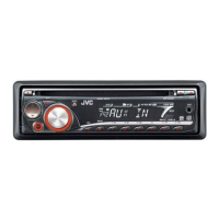
EasyManuals Logo

JVC KD-G321 Schematic Diagrams

JVC KD-G321
50 pages
To Next Page IconTo Next Page
To Previous Page IconTo Previous Page
Page #39 background imageLoading...
Page #39 background image
(No.MA236)1-15
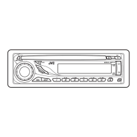
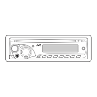
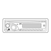
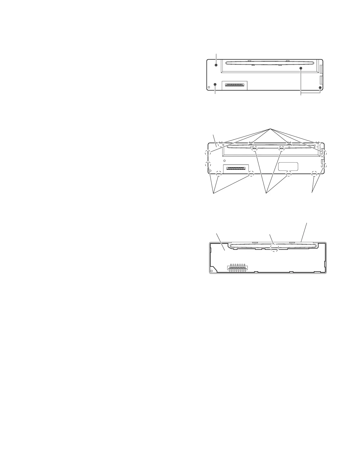
3.1.8 Removing the switch board
(See Figs.8 to 10)
Remove the front panel assembly.
(1) Remove the four screws J on the back side of the front pan-
el assembly. (See Fig.8.)
(2) Release the joints f and remove the rear cover. (See Fig.9.)
(3) Release the joint g and take out the switch board from the
front panel assembly. (See Fig.10.)
Fig.8
Fig.9
Fig.10
J
J
J
Joints f
Joints f
Joints f Joints f
Rear cover
Switch board
Joint
g
Front panel assembly

Other manuals for JVC KD-G321

Questions and Answers:

Question and Answer IconNeed help?

Do you have a question about the JVC KD-G321 and is the answer not in the manual?

JVC KD-G321 Specifications

General IconGeneral
BrandJVC
ModelKD-G321
CategoryCar Receiver
LanguageEnglish

Related product manuals