EasyManuals Logo
Home>JVC>Car Receiver>KD-G401

JVC KD-G401 Service Manual

JVC KD-G401
53 pages
To Next Page IconTo Next Page
To Previous Page IconTo Previous Page
Page #27 background imageLoading...
Page #27 background image
(No.MA051)1-27
5.6 Maintenance of laser pickup
(1) Cleaning the pick up lens
Before you replace the pick up, please try to clean the lens
with a alcohol soaked cotton swab.
(2) Life of the laser diode
When the life of the laser diode has expired, the following
symptoms will appear.
The level of RF output (EFM output: amplitude of eye
pattern) will be low.
(3) Semi-fixed resistor on the APC PC board
The semi-fixed resistor on the APC printed circuit board
which is attached to the pickup is used to adjust the laser
power.Since this adjustment should be performed to match
the characteristics of the whole optical block, do not touch
the semi-fixed resistor.
If the laser power is lower than the specified value, the la-
ser diode is almost worn out, and the laser pickup should
be replaced. If the semi-fixed resistor is adjusted while the
pickup is functioning normally, the laser pickup may be
damaged due to excessive current.
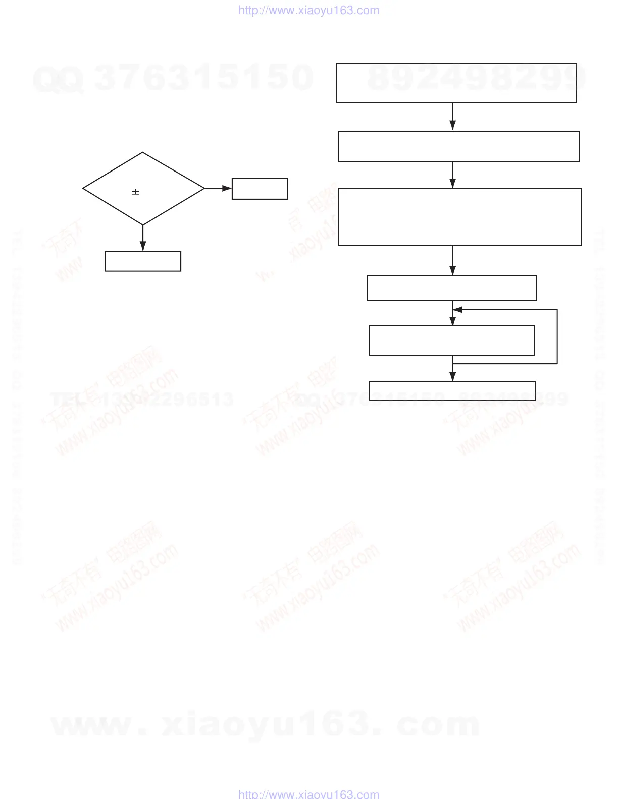
5.7 Replacement of laser pickup
Is RF output
1.3 0.4Vp-p?
YES
NO
OK
Replace it.
Turn of the power switch and, disconnect the
power cord.
Replace the pickup with a normal one. (Refer
to "Removing the pickup unit" on the previous page.)
Plug the power cord in, and turn the power on.
At this time, check that the laser emits for about
seconds and the objective lens moves up and down.
Note: Do not observe the laser beam directly.
Play a disc.
Check the eye-pattern at
RF test point.
Finish.
w
w
w
.
x
i
a
o
y
u
1
6
3
.
c
o
m
Q
Q
3
7
6
3
1
5
1
5
0
9
9
2
8
9
4
2
9
8
T
E
L
1
3
9
4
2
2
9
6
5
1
3
9
9
2
8
9
4
2
9
8
0
5
1
5
1
3
6
7
3
Q
Q
TEL 13942296513 QQ 376315150 892498299
http://www.xiaoyu163.com

Other manuals for JVC KD-G401

Questions and Answers:

Question and Answer IconNeed help?

Do you have a question about the JVC KD-G401 and is the answer not in the manual?

JVC KD-G401 Specifications

Audio Amplifier IconAudio Amplifier
maximum power output (front)50 W per channel
maximum power output (rear)50 W per channel
continuous power output (RMS) (front)19 W per channel into 4 Ω, 40 Hz to 20 000 Hz at no more than 0.8% total harmonic distortion
continuous power output (RMS) (rear)19 W per channel into 4 Ω, 40 Hz to 20 000 Hz at no more than 0.8% total harmonic distortion
load impedance4 Ω (4 Ω to 8 Ω allowance)
tone control range (bass)±10 dB at 100 Hz
tone control range (treble)±10 dB at 10 kHz
frequency response40 Hz to 20 000 Hz
signal-to-noise ratio70 dB
line-out level/impedance2.0 V/20 kΩ load (full scale)
output impedance1 kΩ
CD Player IconCD Player
operating voltageDC 14.4 V (11 V to 16 V allowance)
allowable operating temperature0°C to +40°C
dimensions (W × H × D)182 mm × 52 mm × 150 mm
panel size188 mm × 58 mm × 11 mm
mass1.3 kg (excluding accessories)
frequency response5 Hz to 20 000 Hz
dynamic range96 dB
signal-to-noise ratio98 dB
max. bit rate320 Kbps
Tuner IconTuner
frequency range (FM)87.5 MHz to 108.0 MHz
frequency range (AM MW)522 kHz to 1 620 kHz
frequency range (AM LW)144 kHz to 279 kHz
usable sensitivity11.3 dBf (1.0 µV/75 Ω)
50 dB quieting sensitivity16.3 dBf (1.8 µV/75 Ω)
alternate channel selectivity (400 kHz)65 dB
frequency response40 Hz to 15 000 Hz
stereo separation30 dB
capture ratio1.5 dB
sensitivity (MW)20 µV
selectivity (MW)35 dB
sensitivity (LW)50 µV

Related product manuals