(No.MA147)1-9
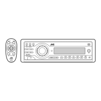
3.1.5 Removing the rear bracket
(See Fig.6)
• Prior to performing the following procedure, remove the bottom
cover.
(1) Remove the three screws E, three screws F and three
screws G attaching the rear bracket on the back side of the
main body.
(2) Take out the rear bracket.
Reference:
When attaching the rear bracket to the main body, insert the
subwoofer output into the slot of the rear bracket.
Fig.6
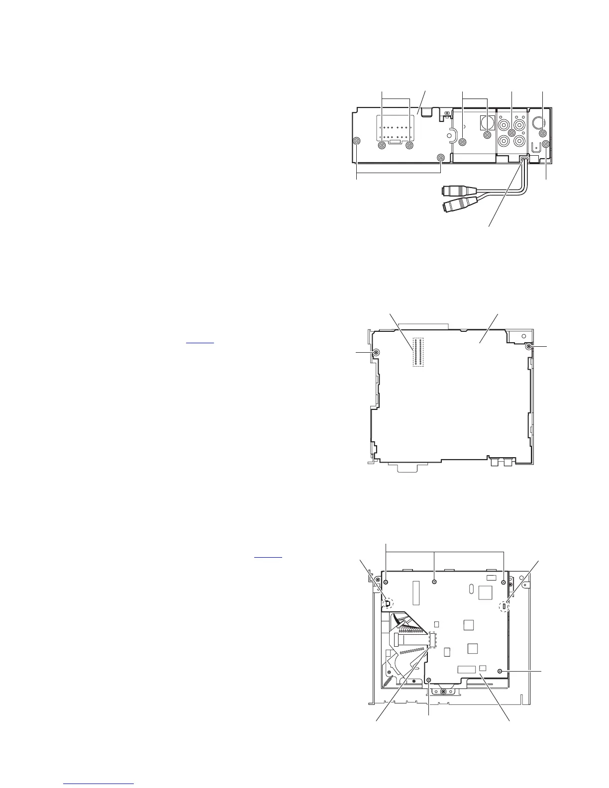
3.1.6 Removing the main board
(See Fig.7)
• Prior to performing the following procedure, remove the front
panel assembly, front chassis assembly, side panel, bottom
cover and rear bracket.
(1) Remove the two screws H attaching the main board.
(2) Disconnect the connector CN501
and take out the main
board.
Fig.7
3.1.7 Removing the CD mecha control board
(See Fig.8)
• Prior to performing the following procedure, remove the front
panel assembly, front chassis assembly, side panel, bottom
cover, rear bracket and main board.
(1) Disconnect the card wire from the connector CN601
on the
CD mecha control board.
(2) Remove the five screws J attaching the CD mecha control
board.
(3) Release the claw f, and take out the CD mecha control
board.
Reference:
When attaching the CD mecha control board, attach it to the
claw f and pass the slot g of it into the boss of the CD mecha-
nism assembly.
Fig.8
F
E E
Rear bracket
GFG
Insert the steering
remote into the slot.
Main board
H
H
CN501
CD mecha control board
CN601
J
J
J
Slot g
Claw f
 Loading...