(No.MA503<Rev.003>)8/16
SECTION 2
SPECIFIC SERVICE INSTRUCTIONS
This service manual does not describe SPECIFIC SERVICE INSTRUCTIONS.
SECTION 3
DISASSEMBLY
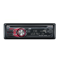
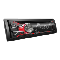
3.1 Main body (Used model: KD-R431)
3.1.1 Removing the Bottom chassis (See Fig.1)
(1) Disengage the 7 hooks a engaging the Bottom chassis.
(2) Slide the Bottom chassis backward to remove it.
Fig.1
3.1.2 Removing the Front chassis (See Fig.2)
(1) Disengage the 4 hooks b engaging both sides of the Front
chassis.
Fig.2
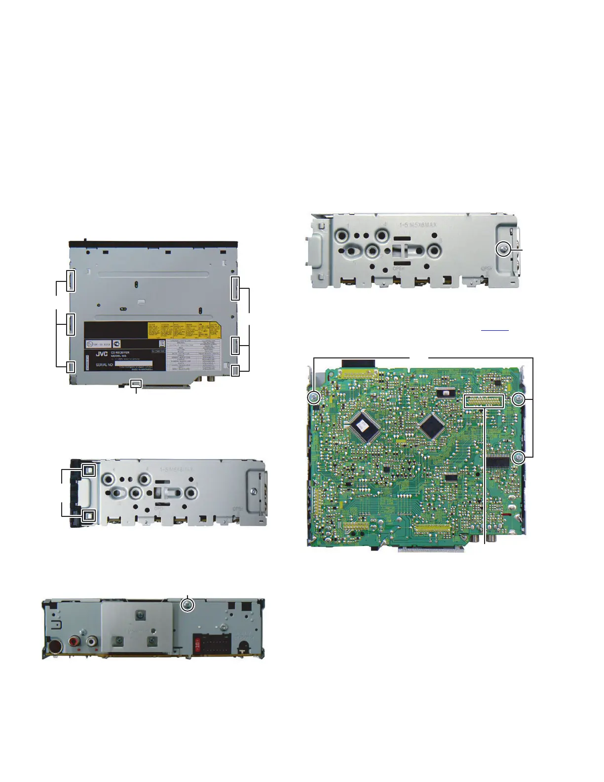
3.1.3 Removing the Erectric unit (See Fig.3, 4 and 5)
(1) Remove the 1 screw A attaching the Rear bracket. (See
Fig.3)
Fig.3
(2) Remove the 2 screws B attaching both sides of the Top
chassis. (See Fig.4)
Fig.4
(3) Remove the 3 screws C attaching the Main board. (See
Fig.5)
(4) Disconnect the board to board connector CN502
connect-
ing the Main board and the CD mechanism. (See Fig.5)
Fig.5
hook
a
hook
a
hook
a
hook b
A
B
C
CN502
 Loading...